3-axis CNC machining is a cornerstone of modern manufacturing, enabling the production of precise parts through computer-controlled tools. This guide provides a detailed examination of its components, processes, technical parameters, and applications, offering a clear and systematic understanding for professionals and engineers. The focus is on technical accuracy, structured clarity, and practical insights for effective implementation in manufacturing environments.
Overview of 3-Axis CNC Machining
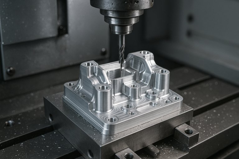
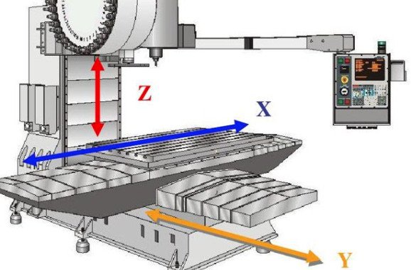
3-axis CNC machining refers to a subtractive manufacturing process where a computer numerical control (CNC) system directs a cutting tool along three linear axes: X (left-right), Y (front-back), and Z (up-down). The workpiece remains stationary while the tool moves to remove material, shaping the desired part. This method is ideal for producing parts with simple to moderately complex geometries, offering high precision and repeatability for industries such as automotive, aerospace, and general engineering.
The process begins with a CAD (Computer-Aided Design) model, which is converted into a CNC program using CAM (Computer-Aided Manufacturing) software. The program generates G-code, instructing the machine on tool paths, speeds, and feeds. 3-axis machines are widely used due to their cost-effectiveness, simplicity, and ability to handle a variety of materials, including metals, plastics, and composites.
Key Components of a 3-Axis CNC Machine
A 3-axis CNC machine comprises several critical components that ensure precision and functionality. Each component plays a specific role in the machining process, contributing to the system’s overall performance.
| Component | Function | Technical Specifications |
|---|---|---|
| Spindle | Rotates the cutting tool at high speeds to remove material. | Speed: 8,000–24,000 RPM; Power: 1–15 kW (material-dependent). |
| Linear Axes (X, Y, Z) | Enable tool movement in three directions for precise positioning. | Travel range: 300–2000 mm (X), 200–1000 mm (Y), 100–500 mm (Z). |
| Controller | Interprets G-code and controls machine movements. | Closed-loop system with absolute/incremental encoders. |
| Worktable | Secures the workpiece during machining. | Size: 300x300 mm to 1000x1000 mm; T-slot for fixturing. |
| Tool Holder | Grips cutting tools securely. | Types: BT30, BT40, HSK; Taper accuracy: ±0.005 mm. |
These components are engineered for durability and precision, with materials like hardened steel for the spindle and high-grade aluminum or steel for the worktable. The controller typically uses closed-loop feedback systems to monitor axis positions, ensuring accuracy within ±0.01 mm.
Machining Process and Workflow
The 3-axis CNC machining process follows a systematic workflow to transform raw materials into finished parts. The key stages include:
- Design Creation: Engineers create a CAD model defining the part’s geometry, dimensions, and tolerances.
- Program Generation: CAM software converts the CAD model into G-code, specifying tool paths, feed rates (100–1000 mm/min), and spindle speeds.
- Machine Setup: The workpiece is secured on the worktable, and the appropriate cutting tool is installed. The machine is “zeroed” to establish a reference point.
- Machining Execution: The CNC controller executes the G-code, moving the tool along the X, Y, and Z axes to cut the workpiece.
- Inspection: Finished parts are measured using calipers, micrometers, or CMMs (Coordinate Measuring Machines) to verify tolerances (±0.05–0.1 mm for standard parts).
Each stage requires precise coordination to minimize errors. For example, improper zeroing can lead to dimensional inaccuracies, while incorrect feed rates may cause tool wear or surface defects.
Technical Parameters in 3-Axis CNC Machining
Technical parameters directly influence the quality, efficiency, and cost of 3-axis CNC machining. Key parameters include spindle speed, feed rate, depth of cut, and tool selection. Below is a table summarizing typical parameters for common materials:
| Material | Spindle Speed (RPM) | Feed Rate (mm/min) | Depth of Cut (mm) | Tool Type |
|---|---|---|---|---|
| Aluminum | 10,000–20,000 | 300–800 | 0.5–2.0 | Carbide end mill |
| Steel | 6,000–12,000 | 100–400 | 0.2–1.0 | HSS or carbide end mill |
| Plastic | 8,000–15,000 | 200–600 | 0.5–3.0 | Single-flute end mill |
| Brass | 10,000–18,000 | 250–700 | 0.5–1.5 | Carbide end mill |
These parameters vary based on tool diameter (e.g., 6–12 mm for end mills), workpiece hardness, and desired surface finish (Ra 0.8–3.2 µm). For instance, aluminum allows higher feed rates due to its softness, while steel requires slower speeds to prevent tool overheating. Proper parameter selection reduces machining time and extends tool life.
Applications of 3-Axis CNC Machining
3-axis CNC machining is versatile, supporting a wide range of applications across industries. Common uses include:
- Automotive: Production of engine components, brackets, and transmission parts with tolerances of ±0.05 mm.
- Aerospace: Machining of aluminum airframe components and titanium fittings requiring high precision.
- Electronics: Fabrication of enclosures, heat sinks, and connectors with fine surface finishes (Ra 0.8 µm).
- General Engineering: Creation of jigs, fixtures, and custom mechanical parts for industrial machinery.
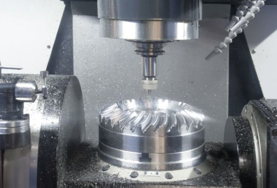
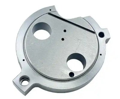
The process excels in producing 2D and 2.5D parts, such as flat plates, housings, and panels. However, it is less suited for complex 3D geometries requiring multi-angle tool access, where 5-axis machining is preferred.
Design Considerations for 3-Axis CNC Machining
Effective part design enhances machinability and reduces costs. Key considerations include:
- Internal Corners: Use radii (e.g., R ≥ 0.5 mm) instead of sharp corners to accommodate cylindrical tools. Smaller radii increase machining time due to the need for smaller tools.
- Wall Thickness: Maintain minimum thicknesses of 0.8 mm for metals and 1.5 mm for plastics to avoid vibrations and deformation.
- Hole Depth: Limit hole depths to 4–5 times the diameter (e.g., 20 mm for a 5 mm drill) to prevent tool deflection.
- Feature Alignment: Align features with X, Y, or Z axes to minimize setups, reducing errors and time.
- Tolerances: Specify standard tolerances (±0.1 mm) unless tighter tolerances are required, as they increase machining and inspection costs.
Submitting a technical drawing with the CAD model clarifies specifications like tolerances, surface finishes (e.g., Ra 1.6 µm), and thread details, ensuring accurate machining.
Limitations of 3-Axis CNC Machining
While versatile, 3-axis CNC machining has constraints that impact its suitability for certain applications:
- Limited Geometry: The fixed workpiece orientation restricts access to complex surfaces, requiring multiple setups for intricate parts.
- Tool Access: Deep cavities or undercuts are challenging, as tools approach from above, limiting reach.
- Setup Time: Multiple setups for multi-sided parts increase machining time and risk of errors (e.g., ±0.02 mm misalignment per setup).
These limitations make 3-axis machining less ideal for parts with complex 3D contours, where 5-axis systems offer greater flexibility.
Optimizing 3-Axis CNC Machining Performance
To maximize efficiency and quality, consider the following strategies:
- Tool Selection: Use carbide tools for harder materials like steel to reduce wear; single-flute tools for plastics to improve chip evacuation.
- Coolant Use: Apply coolant (e.g., water-based emulsions) to reduce heat and improve surface finish, especially for metals.
- Simulation: Use machining simulation software to detect potential collisions, reducing scrap rates (e.g., 1–2% material waste reduction).
- Maintenance: Regularly check spindle alignment (within 0.01 mm) and lubricate linear guides to maintain precision.
Implementing these practices ensures consistent part quality and extends machine lifespan, typically 5–10 years under regular maintenance.
Conclusion
3-axis CNC machining remains a fundamental technology in precision manufacturing, balancing cost, simplicity, and accuracy. Its ability to produce high-quality parts for diverse applications makes it indispensable in industries like automotive and aerospace. By understanding its components, processes, parameters, and design considerations, manufacturers can optimize performance and achieve reliable results. While limited in handling complex geometries, 3-axis machining excels in producing 2D and 2.5D parts with high efficiency and precision.