4-axis CNC machining enhances precision manufacturing by adding a rotational axis to the standard 3-axis setup, enabling complex geometries with fewer setups. This guide provides a detailed, technical exploration of 4-axis CNC machining, covering its mechanics, applications, programming, and setup considerations. Designed for professionals, it emphasizes systematic processes and specific parameters for optimal performance in industries like aerospace, automotive, and medical manufacturing.
Understanding 4-Axis CNC Machining
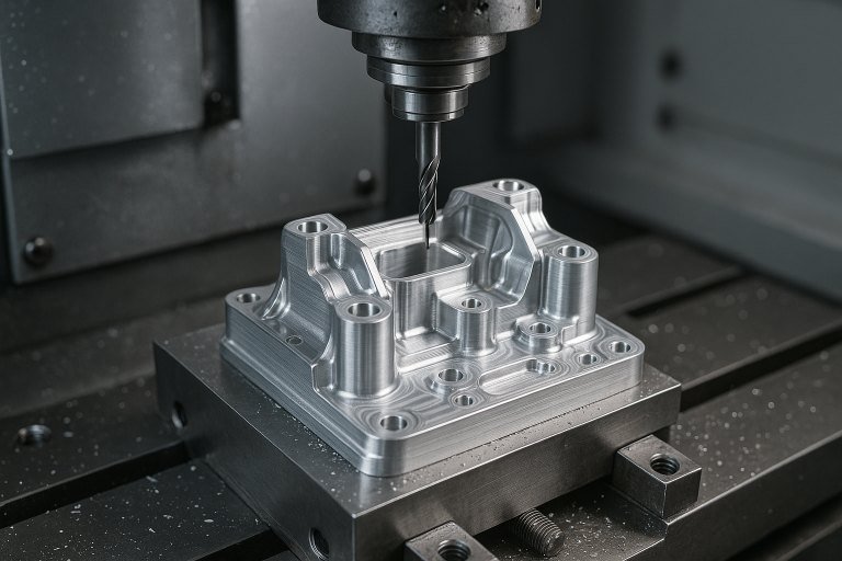
4-axis CNC machining builds on the capabilities of 3-axis systems by incorporating a rotational axis, typically designated as the A-axis (rotating around the X-axis) or B-axis (rotating around the Y-axis). The X, Y, and Z axes handle linear movements, while the additional rotational axis allows the workpiece or tool to rotate, enabling machining on multiple sides without manual repositioning. This configuration reduces setup time, minimizes errors, and enhances precision for complex parts.
The primary advantage lies in its ability to machine intricate features, such as angled surfaces, curved contours, and cylindrical components, in a single setup. Unlike 3-axis machines, which are limited to flat or prismatic parts, 4-axis systems excel in producing components with rotational symmetry or complex profiles. Compared to 5-axis machines, 4-axis setups are more cost-effective while still offering significant versatility for moderately complex parts.
Mechanics of 4-Axis CNC Machining
The mechanics of 4-axis CNC machining involve coordinated movements across four axes: X (left-right), Y (front-back), Z (up-down), and A or B (rotational). The rotational axis is typically achieved through a rotary table or a spindle that rotates the workpiece. The machine’s controller interprets G-code instructions to synchronize linear and rotational movements, ensuring precise cuts.
Key components include:
- Rotary Table: A precision device that rotates the workpiece, often equipped with a chuck or fixture to secure the part.
- Spindle: Houses the cutting tool and provides rotational speed, typically ranging from 6,000 to 24,000 RPM depending on the material and tool.
- Controller: Processes G-code and M-code to manage toolpaths, feed rates, and spindle speeds.
- Servo Motors: Drive the axes with high accuracy, often using closed-loop feedback systems to maintain positional precision within ±0.01 mm.
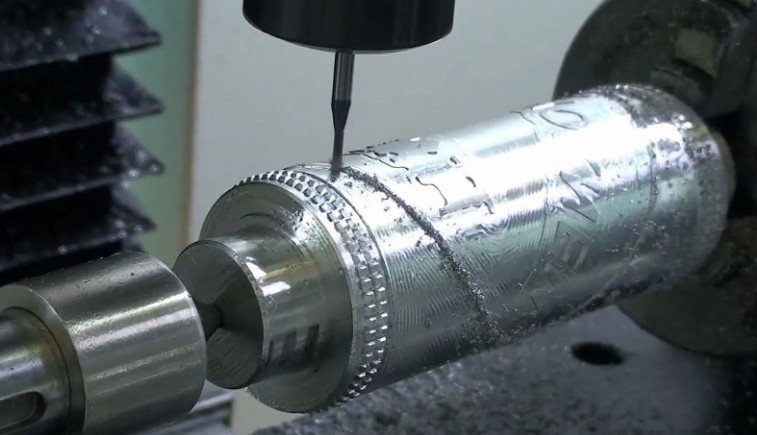
The machine operates in two primary modes: indexing, where the rotary axis positions the workpiece at discrete angles before cutting, and continuous machining, where the workpiece rotates simultaneously with tool movement for complex contours. For example, continuous machining is used for cylindrical features like turbine blades, while indexing suits parts requiring features on multiple sides, such as engine blocks.
Applications of 4-Axis CNC Machining
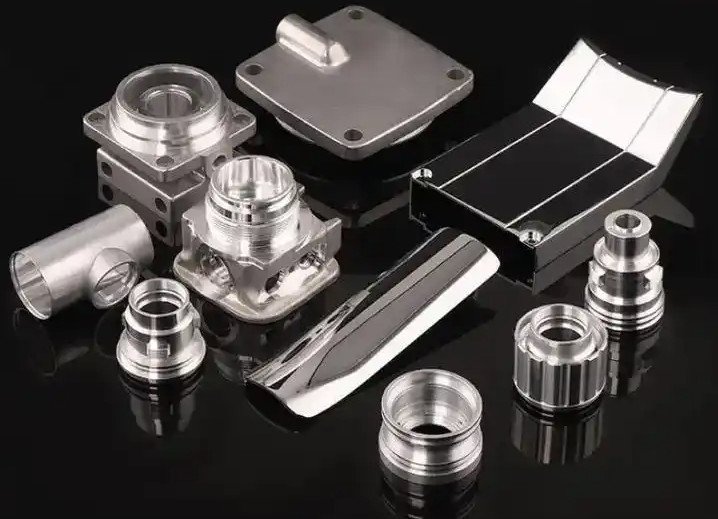
4-axis CNC machining is widely used across industries requiring high-precision components with complex geometries. Its ability to reduce setups and handle rotational features makes it ideal for specific applications.
Aerospace Industry
In aerospace, 4-axis machining produces components like turbine blades, impellers, and structural parts. Turbine blades require smooth, continuous cuts on curved surfaces, achieved through the A-axis rotation. Typical parameters include:
| Component | Material | Tolerance | Spindle Speed (RPM) | Feed Rate (mm/min) |
|---|---|---|---|---|
| Turbine Blade | Titanium | ±0.02 mm | 12,000–18,000 | 300–600 |
| Impeller | Aluminum | ±0.03 mm | 10,000–15,000 | 400–800 |
These components demand tight tolerances and smooth surface finishes (Ra 0.8–1.6 µm) to ensure aerodynamic performance and structural integrity.
Automotive Industry
Automotive applications include engine components, transmission parts, and custom prototypes. Camshafts and cylinder heads benefit from 4-axis machining’s ability to handle complex profiles and angled features. For instance, machining a camshaft involves continuous A-axis rotation to create precise lobe profiles, with spindle speeds of 8,000–12,000 RPM and feed rates of 200–500 mm/min for steel alloys.
Medical Industry
Medical manufacturing uses 4-axis machining for surgical instruments and implants, such as forceps and orthopedic screws. These parts require high precision (tolerances of ±0.01 mm) and smooth finishes (Ra 0.4–0.8 µm) to meet biocompatibility standards. The rotational axis allows for machining complex geometries, like threaded features, in a single setup.
Programming for 4-Axis CNC Machining
Programming a 4-axis CNC machine involves generating G-code and M-code using computer-aided manufacturing (CAM) software, such as Mastercam or Fusion 360. The process starts with a computer-aided design (CAD) model, which is converted into toolpaths defining the tool’s movement across the X, Y, Z, and A axes.
Key programming considerations include:
- Toolpath Generation: CAM software calculates toolpaths for linear and rotational movements. For continuous machining, the A-axis rotation is synchronized with linear axes to maintain constant cutting speed.
- G-Code Commands: Common commands include G00 (rapid positioning), G01 (linear interpolation), G02/G03 (circular interpolation), and G17/G18/G19 (plane selection for arcs). For example, G01 X50 Y20 Z10 A45 F300 commands a linear move to position (50, 20, 10) with a 45-degree A-axis rotation at a feed rate of 300 mm/min.
- Tool Compensation: G41/G42 commands adjust for tool wear, ensuring dimensional accuracy. The offset is stored in the machine’s D-register, typically set to ±0.05 mm for finishing cuts.
- Simulation: Modern CAM software simulates toolpaths to detect collisions, ensuring safe operation. This is critical for 4-axis setups due to the added complexity of rotational movements.
Programmers must specify parameters like spindle speed, feed rate, and depth of cut based on material properties and tool geometry. For example, machining aluminum requires higher spindle speeds (10,000–20,000 RPM) and feed rates (500–1,000 mm/min) compared to stainless steel (6,000–10,000 RPM, 200–400 mm/min).
Setup and Workholding for 4-Axis CNC Machining
Proper setup and workholding are critical for 4-axis CNC machining to ensure accuracy and repeatability. The rotary table or chuck must securely hold the workpiece while allowing precise rotation. Common workholding methods include:
- Chucks: Used for cylindrical parts, providing high clamping force (up to 10,000 N) and centering accuracy (±0.005 mm).
- Fixtures: Custom fixtures align complex parts, ensuring repeatability within ±0.01 mm.
- Vises: Suitable for prismatic parts, with clamping forces of 5,000–8,000 N.
Setup involves defining the workpiece’s zero point, typically at the center of rotation for cylindrical parts. The machine must be calibrated to ensure the rotary axis aligns with the linear axes, with angular accuracy within ±0.01 degrees. Operators use dial indicators or laser alignment tools to verify setup accuracy.
A typical setup sequence includes:
- Secure the workpiece in the chuck or fixture.
- Align the rotary axis using a dial indicator (accuracy ±0.002 mm).
- Set the zero point using the machine’s controller or a touch probe.
- Load the G-code program and perform a dry run to verify toolpaths.
Technical Parameters for 4-Axis CNC Machining
Selecting appropriate parameters ensures optimal performance and part quality. The following table outlines typical parameters for common materials:
| Material | Tool Type | Spindle Speed (RPM) | Feed Rate (mm/min) | Depth of Cut (mm) | Surface Finish (Ra, µm) |
|---|---|---|---|---|---|
| Aluminum | Carbide End Mill | 10,000–20,000 | 500–1,000 | 0.5–2.0 | 0.8–1.6 |
| Stainless Steel | HSS End Mill | 6,000–10,000 | 200–400 | 0.3–1.0 | 0.4–1.2 |
| Titanium | Carbide End Mill | 8,000–12,000 | 100–300 | 0.2–0.8 | 0.4–0.8 |
These parameters vary based on tool diameter, workpiece geometry, and machine capabilities. For instance, a 10 mm carbide end mill cutting aluminum may use a depth of cut of 1.5 mm, while a 6 mm tool cutting titanium may require a reduced depth of 0.5 mm to minimize tool wear.
Limitations of 4-Axis CNC Machining
While 4-axis CNC machining offers significant advantages, it has limitations. The Geneva mechanism, commonly used in rotary tables, restricts continuous machining due to fixed stops, limiting it to indexing for some machines. Additionally, the work envelope is smaller than 5-axis systems, constraining the size and complexity of parts. For example, a typical 4-axis machine has a work envelope of 500 x 500 x 400 mm, compared to 800 x 800 x 600 mm for 5-axis machines. Backlash in the rotary axis, typically ±0.02 degrees, can also affect precision in high-intensity applications.
Comparison with 3-Axis and 5-Axis CNC Machining
4-axis CNC machining strikes a balance between 3-axis and 5-axis systems. 3-axis machines are limited to linear movements, requiring multiple setups for complex parts, which increases time and error risk. 5-axis machines offer greater flexibility with two additional rotational axes, but they are more expensive (30–50% higher cost) and complex to program. 4-axis systems provide a cost-effective solution for parts requiring moderate complexity, with setup times reduced by 20–40% compared to 3-axis machines.
Conclusion
4-axis CNC machining is a versatile and efficient solution for manufacturing complex parts in industries like aerospace, automotive, and medical. By integrating a rotational axis, it reduces setup times, enhances precision, and enables intricate geometries. Understanding its mechanics, applications, programming, and setup requirements allows manufacturers to optimize performance. With proper parameter selection and workholding, 4-axis CNC machining delivers high-quality results for moderately complex components, making it a valuable tool in precision manufacturing.