Worm gears are a critical component in mechanical systems, designed for high torque transmission and significant speed reduction between non-intersecting shafts, typically at 90-degree angles. This article provides a detailed examination of worm gears, including their design, types, materials, technical specifications, and applications. The content is structured to offer a clear, technical, and systematic understanding of worm gears, focusing on their operational principles and practical uses in various industries.
Overview of Worm Gears
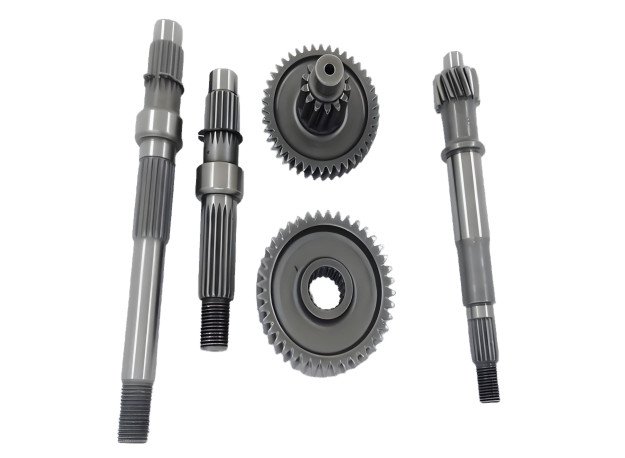
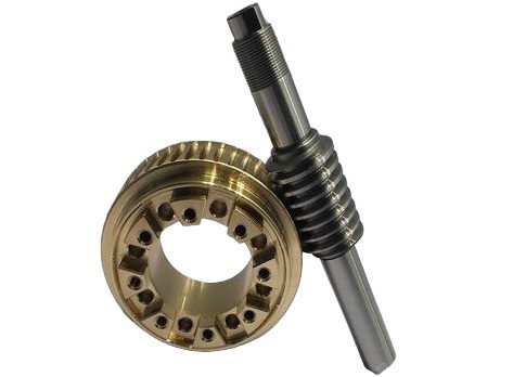
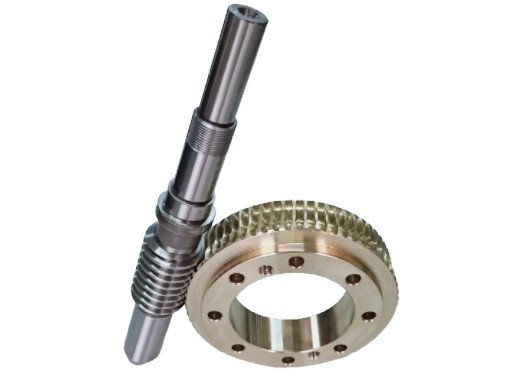
A worm gear consists of two primary components: the worm, which resembles a screw with a spiral thread, and the worm wheel, a toothed gear similar to a spur gear. The worm drives the worm wheel, transferring rotational motion and torque. This configuration allows worm gears to achieve high reduction ratios, often ranging from 10:1 to 300:1, in a compact form, making them ideal for applications where space is limited and high torque is required. The worm’s screw-like action engages the worm wheel’s teeth, resulting in a sliding contact that distinguishes worm gears from other gear types.
The primary advantage of worm gears is their ability to provide significant speed reduction and torque multiplication in a single stage, unlike parallel axis gearing, which may require multiple stages to achieve similar ratios. Additionally, worm gears often exhibit self-locking properties, particularly with single-start worms, preventing the worm wheel from driving the worm. This feature is valuable in applications requiring secure load holding, such as elevators and hoists.
Types of Worm Gears
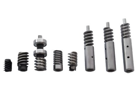
Worm gears are categorized based on their design and construction, each suited to specific applications. The main types include:
- Non-Throated Worm Gears: These have no groove or throat machined around the worm or worm wheel. They are simpler in design but have lower load-carrying capacity, suitable for light-duty applications.
- Single-Throated Worm Gears: The worm wheel is throated, increasing the contact area and load capacity. These are used in moderate-load applications.
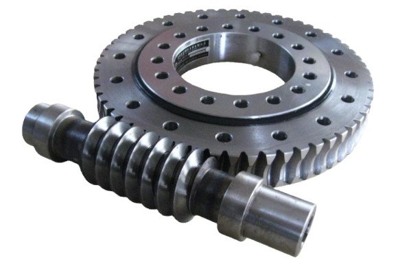
- Double-Throated Worm Gears: Both the worm and worm wheel are throated, providing the highest load-carrying capacity. These are ideal for heavy-duty applications requiring robust torque transmission.
- Double-Enveloping Worm Gears: Also known as globoidal worm gears, these feature a worm with a variable pitch diameter and a fully enveloping worm wheel, maximizing contact and load capacity for high-precision, high-load scenarios.
Technical Specifications
Worm gear design involves several key parameters that determine performance and suitability for specific applications. Below is a table summarizing critical technical specifications:
| Parameter | Description | Typical Values |
|---|---|---|
| Gear Ratio | Ratio of worm wheel teeth to worm starts | 10:1 to 300:1 |
| Center Distance | Distance between worm and worm wheel axes | 25 mm to 500 mm |
| Module (m) | Size of gear teeth, affecting pitch diameter | 0.5 to 20 |
| Lead Angle (γ) | Angle of worm thread relative to axis | 3° to 25° |
| Efficiency | Power output divided by power input | 30% to 85% |
| Torque Output | Maximum torque delivered by worm wheel | Up to 33 Nm for compact designs |
These parameters are calculated based on application requirements, such as input speed, output torque, and operating conditions. For example, the gear ratio is determined by dividing the number of worm wheel teeth (z2) by the number of worm starts (z1). A single-start worm with a 20-tooth worm wheel yields a 20:1 ratio, significantly reducing speed while increasing torque.
Materials and Manufacturing
Worm gears are typically constructed from dissimilar metals to reduce friction and wear. The worm is often made of hardened steel (e.g., case-hardened steel with hardness >58 HRC), while the worm wheel is commonly made of phosphor bronze (e.g., CuSn12) due to its excellent wear resistance and lubricity. This combination minimizes wear under sliding contact, which is predominant in worm gear operation. In lighter applications, plastic worm wheels paired with metal worms are used for their corrosion resistance, lightweight properties, and reduced need for lubrication.
Stainless steel (e.g., 303 or 316 grades) is employed in environments requiring high corrosion resistance, such as food and beverage processing. Plastic gears, while less durable under high loads, are suitable for automotive components and robotics. Manufacturing processes include precision machining, hobbing for worm wheels, and grinding/polishing for worms to ensure smooth surfaces and accurate tooth profiles, critical for efficient operation and minimal backlash.
Lubrication Requirements
Due to the sliding contact between the worm and worm wheel, lubrication is essential to reduce friction, heat, and wear. Common lubricants include:
- Mineral-Based Compounded Gear Oils: These provide good lubricity for general applications but may not suit yellow metals like brass due to additive reactivity.
- Industrial Extreme Pressure (EP) Gear Oils: Suitable for high-load applications but require caution with brass components to avoid leaching.
- Polyalphaolefin (PAO) Gear Lubricants: These offer excellent lubricity and are effective across a wide temperature range, ideal for demanding conditions.
- Polyalkylene Glycol (PAG) Lubricants: These provide superior lubricity and low-temperature performance but are incompatible with mineral oils and certain seals.
Lubricant selection depends on operating temperature, load, and material compatibility. Regular oil analysis is recommended to monitor wear metals and ensure lubricant effectiveness.
Applications of Worm Gears
Worm gears are employed across various industries due to their compact design, high reduction ratios, and self-locking capabilities. Key applications include:
| Industry | Application | Key Benefit |
|---|---|---|
| Elevators and Hoists | Lifting mechanisms | Self-locking prevents load back-driving |
| Automotive | Steering systems, seat adjustments | Compact design fits tight spaces |
| Robotics | Joints and actuators | High precision and torque |
| Medical Devices | Adjustable beds, dental chairs | Quiet operation, compact size |
| Heavy Machinery | Rock crushers, conveyors | Shock load absorption |
| Musical Instruments | Tuning mechanisms | Precise adjustments |
In elevators, the self-locking feature acts as a secondary braking mechanism, enhancing safety. In robotics, miniature worm gear motors provide precise motion control in confined spaces. Heavy machinery benefits from the gears’ ability to absorb shock loads, while musical instruments like guitars use simple worm gears for accurate tuning.
Design Considerations
Designing worm gears requires careful consideration of several factors to ensure performance and longevity:
- Gear Ratio Selection: The ratio must balance speed reduction and torque requirements, with higher ratios increasing self-locking but reducing efficiency.
- Thermal Management: Sliding contact generates significant heat, necessitating adequate lubrication and gearbox cooling, such as external fins or forced air flow.
- Material Selection: The choice of materials impacts wear, efficiency, and cost. Hardened steel and bronze are standard, but application-specific needs may require stainless steel or plastic.
- Backlash Control: Precision manufacturing minimizes backlash, ensuring smooth operation and accurate positioning in applications like robotics.
- Load Capacity: The gear design must account for expected loads, with double-throated or double-enveloping gears used for high-load scenarios.
Efficiency is a critical consideration, as worm gears typically range from 30% to 85%, depending on the lead angle and lubrication. For example, a lead angle of 3° may result in efficiencies as low as 30%, while a 25° angle can achieve up to 85%.
Limitations of Worm Gears
While worm gears offer significant advantages, they have limitations that must be addressed:
- Low Efficiency: The sliding contact results in efficiencies of 30% to 85%, lower than spur or helical gears, leading to higher energy losses.
- Heat Generation: The sliding action produces substantial heat, requiring robust lubrication and cooling systems to prevent overheating.
- Wear: The worm wheel, typically made of softer material, experiences wear over time, necessitating periodic replacement to maintain performance.
- Cost: Precision manufacturing and material requirements can make worm gears more expensive than simpler gear types.
These limitations are mitigated through careful design, material selection, and maintenance practices, ensuring reliable operation in suitable applications.
Conclusion
Worm gears are a versatile and robust solution for applications requiring high torque, significant speed reduction, and compact design. Their unique ability to provide self-locking, quiet operation, and shock load absorption makes them indispensable in industries such as elevators, robotics, automotive, and heavy machinery. By understanding their types, technical specifications, materials, and design considerations, engineers can select and implement worm gears effectively to meet specific performance requirements. Proper lubrication and thermal management are critical to maximizing efficiency and lifespan, ensuring worm gears remain a reliable choice for power transmission.