Turbo impellers, also known as turbocharger impellers or compressor wheels, are pivotal components in turbomachinery, including turbochargers, pumps, and compressors. They compress intake air to enhance engine performance, improve fuel efficiency, and reduce emissions. This guide provides a comprehensive overview of turbo impeller types, design principles, material selection, manufacturing processes, performance metrics, and applications, serving as a technical resource for engineers and industry professionals.
Definition and Core Functions of Turbo Impellers
A turbo impeller is a rotating component designed to accelerate and compress fluid (typically air or liquid), converting mechanical energy into fluid kinetic energy. In turbochargers, it is driven by exhaust gases via a turbine wheel connected by a shaft, spinning at high speeds (100,000–250,000 RPM) to draw in ambient air and deliver compressed air to the engine’s combustion chamber. This process increases air density, allowing more fuel to be burned, which boosts horsepower and torque without increasing engine size. Key functions include:
- Air Compression: The impeller compresses intake air to a pressure ratio of 1.5:1 to 4:1, enabling higher combustion efficiency.
- Increased Engine Power: By facilitating more complete fuel combustion, impellers can increase engine power by 30–50% or more, depending on design and application.
- Improved Efficiency: Recycling exhaust energy enhances fuel economy compared to naturally aspirated engines of similar power output.
- Emission Reduction: Enhanced combustion efficiency reduces unburned fuel, lowering emissions in automotive and industrial applications.
Types of Turbo Impellers
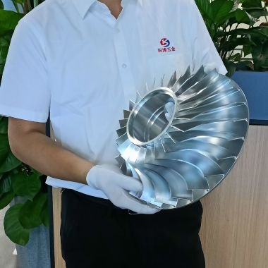
Turbo impellers are classified based on geometry, flow direction, and structural features. Common types include open, semi-closed, closed, axial flow, and radial flow impellers, each suited to specific applications.
| Impeller Type | Description | Applications | Advantages | Limitations |
|---|---|---|---|---|
| Open Impeller | Hub with vanes, no side walls, open inlet (eye). | Pumps with solids, small compressors. | Easier inspection, less clogging. | Lower efficiency, weaker structure. |
| Semi-Closed Impeller | Back wall for strength, partially enclosed vanes. | Mixed solid-liquid pumps, medium compressors. | Improved strength, moderate efficiency. | Lower efficiency than closed impellers. |
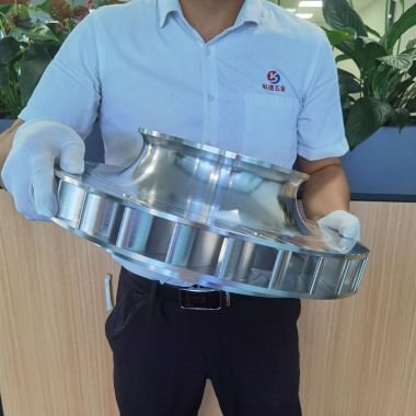
| Closed Impeller | Enclosed vanes with front and back walls. | High-pressure pumps, turbochargers. | High efficiency, robust structure. | Complex manufacturing, higher cost. |
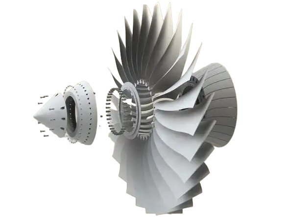
| Axial Flow Impeller | Blades parallel to hub, axial flow direction. | Jet engines, large turbines. | High airflow, stable performance. | Limited to high-flow applications. |
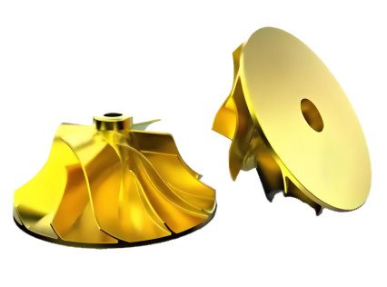
| Radial Flow Impeller | Flow enters axially, exits radially. | Automotive turbochargers, centrifugal pumps. | High pressure boost, compact design. | Complex flow dynamics. |
Design Considerations for Turbo Impellers
Designing turbo impellers requires optimizing geometry, blade configuration, and flow dynamics to achieve high efficiency and performance. Key parameters include specific speed, meridional contour, blade design, and aerodynamic shape.
Specific Speed Range
Specific speed (nq or Ns) guides impeller selection and is calculated as:
nq = (N * Q^0.5) / H^0.75 (EU) or Ns = (N * Q^0.5) / H^0.75 (US), where:
- N = Rotational speed (RPM)
- Q = Flow rate (m³/s or GPM)
- H = Head (m or ft)
Turbo impellers typically operate within a specific speed range of 8 < nq < 500 (EU) or 400 < Ns < 25,000 (US), determining whether radial, mixed, or axial flow designs are appropriate.
Meridional Contour
The meridional contour defines the impeller’s axial and radial shape, designed using Bezier polynomials or arcs to ensure smooth fluid flow and minimize losses. Hub and tip diameters are calculated to balance flow capacity and pressure rise, with typical hub-to-tip ratios ranging from 0.3 to 0.6.
Blade Design and Aerodynamic Shape
Blade geometry, including leading and trailing edge angles, is critical for efficiency. Leading edge angles (10°–30°) minimize incidence losses, while trailing edge design incorporates slip factor correlations to optimize energy transfer. Curved blades reduce air resistance, and splitter blades may be added for high-flow applications. Impeller dimensions, such as diameter (50–200 mm in automotive turbochargers) and blade count (6–12), are tailored to engine displacement and performance goals (e.g., low-end torque vs. high-RPM power).
Airfoil vs. Meanline Design
Two design approaches are used:
- Airfoil Design: Applied to axial impellers, with blades shaped to minimize drag and optimize lift, resembling jet engine compressors.
- Meanline Design: Common for radial impellers, focusing on streamline flow along the blade’s mean camber line.

Material Selection for Turbo Impellers
Turbo impellers operate under extreme conditions, including high rotational speeds, temperatures (up to 1,000°C in turbochargers), and centrifugal forces, necessitating materials with superior mechanical properties.
| Material | Properties | Applications | Yield Strength (MPa) | Max Operating Temp (°C) |
|---|---|---|---|---|
| Billet Aluminum | Lightweight, high strength, fine grain structure. | Automotive turbochargers, lower-performance systems. | 400–500 | 200 |
| Titanium Alloy | High strength-to-weight ratio, corrosion resistance. | Aerospace, high-performance turbochargers. | 900–1200 | 600 |
| Stainless Steel | Corrosion resistance, high tensile strength. | Marine, heavy-duty trucks, industrial machinery. | 600–800 | 800 |
| Inconel 718 | Heat and pressure resistance, durability. | High-temperature turbochargers, aerospace. | 1000–1200 | 700–1000 |
Material choice depends on application demands. Aluminum alloys are used in lower-performance systems for their lightweight properties, while titanium and Inconel 718 are preferred for high-temperature and high-performance applications due to their strength and thermal resistance.
Manufacturing Processes and Challenges
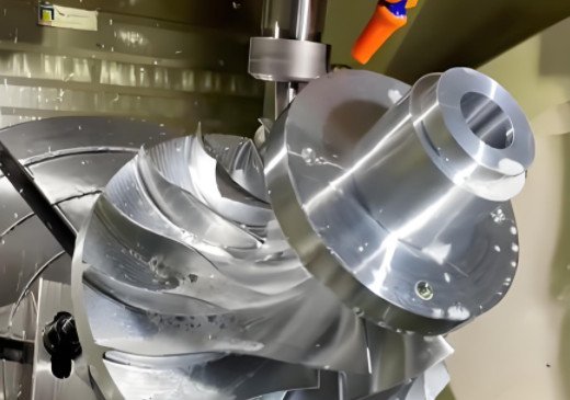
Manufacturing turbo impellers requires precision to achieve tight tolerances (±0.001 mm) and ensure aerodynamic efficiency and durability. Key processes include:
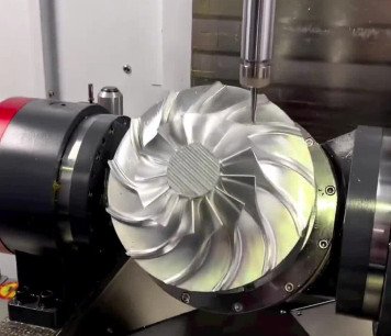
- 5-Axis CNC Machining: Used to create complex blade geometries with high precision, especially for billet aluminum and titanium impellers.
- Vacuum Investment Casting: Employed for Inconel and stainless steel impellers to achieve intricate shapes and high strength.
- Forging: Enhances material density and strength, particularly for high-performance applications.
- Heat Treatment: Applied to alloys to improve resistance to thermal fatigue and enhance mechanical properties under high temperatures.
- Dynamic Balancing: Critical to prevent vibration at high speeds (100,000–250,000 RPM). Even minor imbalances can cause bearing wear or catastrophic failure. Balancing involves adding or removing material from the hub or nose.
Challenges include maintaining dimensional accuracy, managing thermal stresses during casting, and ensuring uniform material properties to withstand centrifugal forces.
Performance Parameters
Turbo impeller performance is evaluated through metrics that determine efficiency and effectiveness in turbomachinery systems.
Pressure Ratio
The pressure ratio (outlet to inlet pressure) typically ranges from 1.5:1 to 4:1 in automotive turbochargers, influenced by impeller diameter, blade design, and rotational speed (50,000–250,000 RPM).
Flow Rate
Flow rate, measured in cubic feet per minute (CFM) or m³/s, quantifies fluid volume moved. High-flow impellers machining in twin-scroll turbochargers achieve 500–1000 CFM, tailored to engine size and boost requirements.
Efficiency
Impeller efficiency (useful work output to energy input) ranges from 70% to 85% in optimized systems. Efficiency is enhanced by optimizing blade angles, reducing turbulence, and minimizing leakage losses.
Rotational Speed and Balance
High rotational speeds require precise balancing to prevent vibration and bearing wear. Balance cuts on the hub or nose ensure stability above critical speeds.
Throttle Response and Turbo Lag
Smaller, lighter impellers or twin-turbo setups reduce turbo lag, improving throttle response in automotive applications, particularly for low-end torque.
Applications of Turbo Impellers
Turbo impellers are used across diverse industries, each with specific requirements:
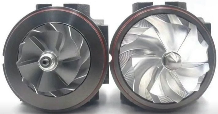
- Automotive: Radial flow impellers in turbochargers (e.g., BMW, Toyota) boost engine power by 30–50%, achieving pressure ratios of 2:1 to 3:1.
- Aerospace: Axial impellers in jet engines and aircraft turbochargers provide high airflow, operating at temperatures up to 600–1000°C.
- Marine: Turbocharged ship engines use stainless steel impellers to withstand corrosive environments.
- Industrial Machinery: Centrifugal pumps and turbocompressors in power generation and HVAC systems use closed impellers for high-pressure fluid transfer.
Issues in Turbo Impeller Performance
While designed for reliability, turbo impellers face several performance issues:
- Blade Damage: High-speed rotation and foreign object ingestion can cause erosion or cracking, reducing efficiency.
- Vibration: Unbalanced impellers lead to excessive vibration, accelerating bearing wear and risking failure.
- Thermal Stress: Prolonged exposure to high temperatures (700–1000°C) can deform materials like aluminum if not properly managed.
- Cavitation: In pumps, low-pressure zones cause vapor bubble formation, leading to surface damage and reduced performance.
- Turbo Lag: Larger impellers may delay throttle response, particularly in automotive applications, impacting drivability.
These issues are mitigated through robust material selection, precise balancing, heat treatment, and regular maintenance.
Maintenance and Inspection
Regular maintenance ensures impeller longevity. Open impellers are easier to inspect due to exposed vanes, while closed impellers require disassembly. Key practices include:
- Checking for blade wear, erosion, or cracks.
- Verifying dynamic balance to prevent vibration.
- Inspecting for thermal fatigue or material deformation.
- Cleaning to remove debris and prevent clogging.

Conclusion
Turbo impellers are engineering marvels that combine aerodynamics, material science, and precision manufacturing to enhance turbomachinery performance. By understanding impeller types, design principles, materials, manufacturing challenges, and performance metrics, engineers can optimize systems for efficiency, power, and reliability across automotive, aerospace, marine, and industrial applications. Proper maintenance and robust design mitigate performance issues, ensuring turbo impellers remain a cornerstone of modern engineering solutions.
Turbo Impellers FAQ
What is a turbo impeller?
A turbo impeller is a rotating component in turbomachinery (such as turbochargers, pumps, or compressors) designed to transfer energy between a fluid (liquid or gas) and the machine. It uses curved blades to accelerate or compress the fluid, converting rotational motion into fluid flow or pressure.
How does a turbo impeller differ from a turbine wheel?
While both are rotating components in turbomachinery:
A turbo impeller typically adds energy to a fluid (e.g., compressing air in a turbocharger’s compressor stage).
A turbine wheel extracts energy from a fluid (e.g., using exhaust gases to drive the turbocharger’s rotation).
In many systems (like turbochargers), they work together: the turbine wheel is driven by exhaust gases, which then spins the impeller to compress intake air.
What materials are turbo impellers made from?
Aluminum alloys: Used in low-stress applications (e.g., small turbochargers for passenger cars) due to their lightweight properties.
Titanium alloys: Ideal for high-temperature, high-stress environments (e.g., aerospace turbomachinery) because of their strength and heat resistance.
Stainless steel: Common in corrosive environments (e.g., chemical pumps) for its anti-rust properties.
Nickel-based superalloys: Used in extreme conditions (e.g., gas turbines) to withstand high temperatures and oxidation.
How are turbo impellers manufactured?
Common methods include:
Casting: Molten metal is poured into molds (cost-effective for complex shapes).
Machining: Precision cutting (e.g., CNC milling) for high accuracy, often used for high-performance or custom designs.
3D printing: Emerging for prototyping or specialized materials, allowing intricate blade geometries.
Post-production processes like balancing and surface finishing ensure smooth operation and durability.