The Center Housing Rotating Assembly (CHRA) is the heart of a turbocharger, enabling enhanced engine performance through forced induction. This guide provides a comprehensive, technical exploration of CHRA turbo components, their operation, maintenance requirements, and replacement procedures. Aimed at automotive technicians and enthusiasts, it delivers systematic, data-driven insights to ensure optimal turbocharger functionality.
Understanding the CHRA Turbo
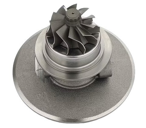
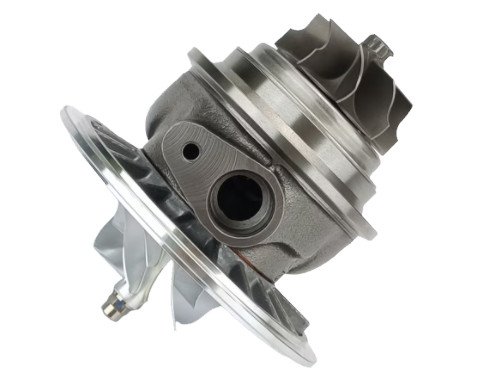
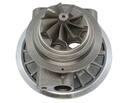
The CHRA is the core assembly of a turbocharger, integrating the turbine wheel(impeller), compressor wheel, and shaft within a central housing. It harnesses exhaust gas energy to compress intake air, boosting engine power by 30-50% compared to naturally aspirated engines. Operating at shaft speeds up to 250,000 RPM and turbine-side temperatures exceeding 950°C, the CHRA demands precision engineering and robust maintenance.
Primary roles include:
- Transforming exhaust energy into rotational force.
- Compressing intake air to enhance combustion efficiency.
- Maintaining dynamic balance under extreme conditions.
Key Components of a CHRA Turbo
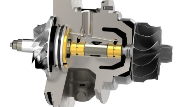
The CHRA comprises several critical components, each designed for specific functions. Below is a detailed breakdown:
| Component | Description | Material | Function |
|---|---|---|---|
| Turbine Wheel | Spins under exhaust gas pressure. | Inconel or titanium alloy | Drives the shaft using exhaust energy. |
| Compressor Wheel | Compresses ambient air. | Aluminum alloy | Increases intake air density. |
| Shaft | Links turbine and compressor. | High-tensile steel | Transmits rotational energy. |
| Bearings | Journal or ball bearings for shaft support. | Steel or ceramic | Minimizes friction, ensures stability. |
| Center Housing | Contains bearings and fluid passages. | Cast iron or aluminum | Supports and cools the assembly. |
| Seals | Prevent fluid and gas leaks. | Carbon or piston rings | Maintains system integrity. |
Operational Mechanism of a CHRA Turbo
The CHRA turbo functions through a precise sequence of mechanical actions:
- Exhaust Gas Entry: Exhaust gases flow into the turbine housing, impacting the turbine wheel.
- Turbine Spin: The turbo impeller rotates the shaft at speeds up to 250,000 RPM.
- Air Compression: The shaft drives the compressor wheel, which draws and compresses ambient air.
- Air Delivery: Compressed air (0.5-2.0 bar boost) is delivered to the engine’s intake manifold.
- Lubrication and Cooling: Oil (1-4 bar pressure) and coolant circulate through the center housing to lubricate bearings and manage heat.
Key operational parameters:
- Boost Pressure: 0.5-2.0 bar, adjustable via wastegate or variable geometry.
- Compressor Efficiency: 65-75% for standard automotive turbos.
- Turbine A/R Ratio: 0.35-1.0, influencing response time and power band.
Potential Problems with CHRA Turbos
Due to high-speed operation and thermal stress, CHRA turbos may develop issues. Common problems include:
- Oil Starvation: Insufficient oil flow (<1 bar at idle) causes bearing wear. Use synthetic oil (e.g., 5W-40) and check feed lines.
- Seal Degradation: Worn seals result in oil leaks, producing blue exhaust smoke. Replace seals during CHRA overhaul.
- Shaft Imbalance: Damaged wheels or debris cause vibration. Maximum axial play: 0.08 mm; radial play: 0.4 mm.
- Overheating: Excessive exhaust gas temperatures (>900°C) damage turbine blades. Monitor EGT with a gauge.
Proactive maintenance can prevent these issues, ensuring a CHRA lifespan of 120,000-180,000 miles.
Maintenance Protocols for CHRA Turbos
Regular maintenance is critical for CHRA longevity. Follow these procedures:
1. Lubrication System Care
Use high-quality synthetic oil (API SP, 5W-30 or 5W-40). Change oil every 6,000 miles and replace filters simultaneously. Ensure oil pressure remains above 1 bar at idle to prevent bearing damage.
2. Air Intake Maintenance
Inspect and replace air filters every 15,000 miles. A restricted filter increases compressor effort, reducing efficiency by up to 10%.
3. Turbo Cool-Down
Idle the engine for 60-90 seconds after spirited driving to lower turbine temperatures, preventing oil coking in bearings.
4. Periodic Inspections
Check for oil leaks, shaft play, and unusual noises every 20,000 miles. Use a dial indicator to measure shaft movement (axial: <0.08 mm; radial: <0.4 mm).
5. Boost System Monitoring
Install a boost gauge to track pressure. Overboost (>2.2 bar) indicates wastegate issues, risking CHRA damage.
CHRA Turbo Replacement Procedure
When repairs are insufficient, replace the CHRA using these steps:
- Diagnosis: Verify failure with tools like a boost tester or endoscope. Symptoms include low boost (<0.5 bar) or excessive smoke.
- CHRA Selection: Match the CHRA to the turbo model (e.g., Holset HX35, Garrett GT30). Confirm specs like turbine inducer (52 mm) and compressor exducer (65 mm).
- Turbo Removal: Disconnect oil, coolant, and exhaust lines. Remove the turbo using tools like a 12 mm wrench or T30 Torx.
- CHRA Swap: Disassemble the turbo, replace the CHRA, and reassemble. Torque housing bolts to 18-22 Nm.
- Oil Priming: Crank the engine without starting for 15 seconds to prime oil lines.
- Testing: Start the engine, check for leaks, and road-test to verify boost (0.8-1.8 bar).
CHRA replacement costs $400-$900, with labor requiring 5-7 hours.
CHRA Turbo Model Specifications
Choosing the correct CHRA depends on engine requirements. Below is a comparison:
| CHRA Model | Turbine Inducer (mm) | Compressor Exducer (mm) | Max Boost (bar) | Application |
|---|---|---|---|---|
| Garrett GT30 | 55.0 | 65.0 | 2.0 | 2.5L-3.5L gasoline engines |
| Holset HX35 | 54.0 | 60.0 | 1.6 | 2.0L-3.0L diesel engines |
| Turbo Technics S200 | 50.0 | 58.0 | 1.4 | 1.8L-2.2L gasoline engines |
Optimizing CHRA Turbo Performance
To ensure long-term reliability, adopt these practices:
- Use premium oil and filters to maintain lubrication quality.
- Install a high-efficiency air filter to reduce compressor workload.
- Avoid frequent cold starts; allow the engine to warm up for 30 seconds.
- Monitor exhaust gas temperatures (<850°C for gasoline engines).
- Conduct professional turbo inspections every 60,000 miles.
Summary
The CHRA turbo is a precision-engineered component critical for engine performance. By understanding its structure, operation, and maintenance needs, users can achieve reliable operation and extended service life. Regular maintenance, careful monitoring, and proper replacement procedures are essential to prevent issues and maintain efficiency.
Frequently Asked Questions about CHRA in Turbochargers
What is a CHRA in a turbocharger?
The CHRA, or Center Housing Rotating Assembly, is the central component of a turbocharger. It houses the rotating shaft, turbine wheel, compressor wheel, bearing system, and shaft seals. The CHRA serves as the connection between the turbine section (where exhaust gases enter) and the compressor section (where air is compressed). It's responsible for transferring the rotational energy from the turbine, driven by exhaust gases, to the compressor, which compresses the incoming air. Without a properly functioning CHRA, the turbocharger cannot effectively convert exhaust energy into compressed air for the engine's intake.
What are the differences in CHRA specifications for different types of turbochargers?
Automotive Passenger Vehicle Turbo: High shaft speeds (150,000 - 250,000 RPM), high turbine inlet temperatures (850°C - 1,050°C), can use floating bush or ball bearings, oil pressure requirement of 3 - 5 bar, and a relatively lightweight CHRA (1.5 - 3 kg).
Heavy - Duty Truck Turbo: Lower shaft speeds (80,000 - 120,000 RPM), lower turbine inlet temperatures (650°C - 800°C), typically use heavy - duty floating bush bearings, higher oil pressure (4 - 7 bar), and a heavier CHRA (5 - 10 kg).
Industrial/Marine Turbo: Even lower shaft speeds (30,000 - 60,000 RPM), lower turbine inlet temperatures (500°C - 700°C), may use floating bush or hydrodynamic bearings, high oil pressure (5 - 10 bar), and a much heavier CHRA (15 - 50 kg).
What are the key components of a CHRA?
Rotating Shaft: Made from high - strength, heat - resistant alloys like Inconel 718 or 17 - 4 PH stainless steel. It connects the turbine wheel to the compressor wheel and transmits rotational energy. Shaft diameters in automotive turbochargers typically range from 5mm to 12mm, with a surface finish of 0.08μm to 0.16μm Ra to minimize friction.
Turbine Wheel: Attached to one end of the shaft, it captures the kinetic energy of exhaust gases. Made of materials like nickel - based superalloys (e.g., Inconel 625 for up to 950°C applications) or cobalt - chromium alloys (e.g., HS - 188 for up to 1,050°C). It has 6 - 12 aerodynamically shaped blades and can be either radial - flow (common in automotive) or axial - flow (in larger industrial/marine units).
Compressor Wheel: Mounted on the other end of the shaft, it compresses ambient air. Usually made of aluminum alloys (e.g., 2618 - T6) or titanium in high - performance applications. It has 12 - 18 backward - curved blades, with a pressure ratio ranging from 1.5:1 to 4.0:1 and a mass flow rate of 0.1 kg/s to 2.0 kg/s.
Bearing System: There are two main types. Floating bush bearings, common in automotive turbochargers, "float" in an oil film and have clearances of 0.05mm to 0.10mm. Ball bearings, used in high - performance applications, offer reduced friction but require tighter clearances (0.02mm to 0.05mm).
Center Housing: Encloses the rotating components. Made of gray cast iron (cost - effective) or nodular cast iron (higher strength). It has passages for oil (3 - 5 bar pressure) and coolant (flow rate of 2 - 4 liters per minute in water - cooled units) and seal galleries.
Shaft Seals: Piston ring seals (metal rings in grooves on the shaft) and carbon seals (graphite - impregnated carbon rings) prevent oil from leaking into the turbine or compressor housings.