Gear shafts are critical mechanical components that integrate the functions of a shaft and a gear, facilitating the transmission of rotational motion and torque in various systems. These cylindrical rods, with gears either integrally formed or attached, are essential for converting speed and torque, ensuring efficient operation in machinery. This comprehensive guide explores gear shaft types, materials, design considerations, manufacturing processes, applications, maintenance, and quality control, providing detailed technical insights for engineers, students, and professionals.
Definition and Function
Gear shafts are cylindrical components that combine a shaft’s load-bearing capacity with a gear’s ability to transmit power. They transfer torque from a power source, such as an engine or motor, to driven components, enabling speed and torque conversion. For instance, in a bicycle’s derailleur system, gear shafts adjust speed ratios by engaging different gears, while in automotive transmissions, they transfer power to wheels, handling torques up to 3500 Nm in heavy-duty vehicles. Their design ensures minimal energy loss, precise motion control, and reliable performance under varying loads.
The function of gear shafts extends beyond simple power transmission. They maintain alignment between rotating components, reduce vibration, and support dynamic loads. In high-precision systems, such as aerospace actuators, gear shafts ensure smooth operation with tolerances as tight as ±0.01 mm, critical for safety and efficiency.
Importance in Mechanical Systems
Gear shafts are ubiquitous across industries, including automotive, aerospace, manufacturing, and renewable energy. In automotive systems, they are integral to engines, transmissions, and differentials, ensuring precise power delivery. For example, a transmission gear shaft in a truck handles torques of 2000-3500 Nm, optimizing fuel efficiency by up to 10%. In manufacturing, gear shafts drive lathes, milling machines, and conveyor systems, supporting continuous operation with minimal downtime. In aerospace, they are used in turbine engines and landing gear mechanisms, requiring high precision and reliability under extreme conditions (e.g., temperatures up to 500°C).
Proper gear shaft design enhances system performance by reducing energy losses, minimizing noise and vibration, and extending machinery lifespan. A poorly designed shaft can lead to issues like misalignment, causing uneven wear and premature failure. For instance, a misaligned gear shaft in a conveyor system can increase power consumption by 20% and reduce gear life by 30%. Thus, understanding gear shaft design and maintenance is crucial for optimizing mechanical systems.
Types of Gear Shafts
Gear shafts are classified by gear type and shaft function, each tailored to specific applications and mechanical requirements.
Classification by Gear Type
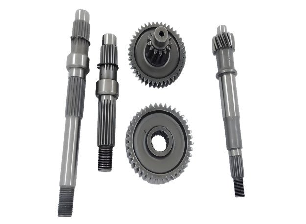
Spur Gear Shafts: Featuring straight teeth parallel to the shaft axis, spur gear shafts are simple and cost-effective to manufacture. They are used in low- to medium-speed applications, such as handheld drills or conveyor systems, with torque capacities typically below 1000 Nm. Their straightforward design allows tolerances of ±0.05 mm but generates higher noise and vibration compared to other types, limiting their use in high-speed systems.
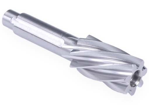
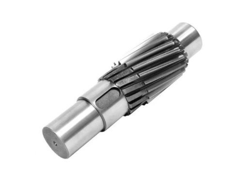
Helical Gear Shafts: With teeth cut at an angle (typically 15-30°), helical gear shafts provide smoother, quieter operation due to gradual tooth engagement. They are ideal for high-speed, high-torque applications like automotive transmissions and industrial gearboxes, handling torques up to 5000 Nm. Their complex geometry increases manufacturing costs but reduces vibration by up to 40% compared to spur gears.
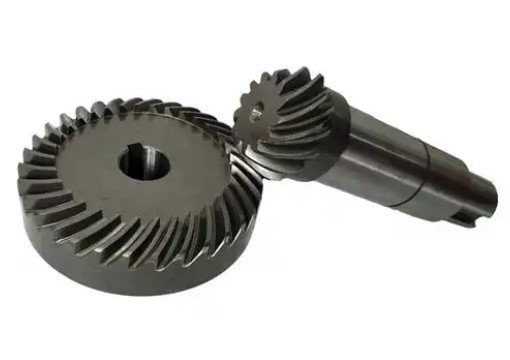
Bevel Gear Shafts: These feature conical teeth for power transmission between intersecting shafts, typically at 90°. Straight bevel gears are simpler, while spiral bevel gears offer smoother operation. Used in vehicle differentials and industrial pumps, they handle torques of 500-3000 Nm. Their design requires precise alignment (within ±0.02 mm) to avoid uneven loading.
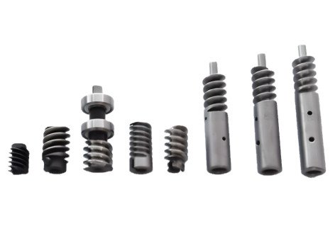
Worm Gear Shafts: Comprising a screw-like worm and a worm wheel, these provide high gear reduction ratios (up to 100:1) and self-locking capabilities. They are used in elevators and heavy-load conveyors, with torque capacities up to 10,000 Nm. Their high friction requires robust lubrication to prevent wear.
Classification by Shaft Function
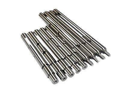
Transmission Shafts: These primary shafts transfer power from a source to other components, such as a drive shaft in a rear-wheel-drive vehicle, transmitting torque from the transmission to the differential (up to 3000 Nm). They are designed for high strength and stiffness to handle dynamic loads.
Countershafts: Used as intermediate shafts, countershafts adjust speed or direction in multi-speed systems like manual transmissions. They provide gear ratios from 1:1 to 5:1, enabling flexible speed and torque output in applications like lathes or automotive gearboxes.
Idler Shafts: These maintain gear meshing or change rotation direction without significant power transmission. In bicycle derailleur systems, idler shafts ensure chain tension, handling minimal torque but requiring precise alignment (within ±0.03 mm) to prevent chain slippage.
Design Considerations
Designing gear shafts requires balancing mechanical and geometric parameters to meet application-specific requirements while ensuring reliability.
Mechanical Requirements
Torque Transmission: Accurate torque calculation is essential to prevent failure. Torque is calculated as \( T = \frac{P}{\omega} \), where \( P \) is power (W) and \( \omega = \frac{2\pi n}{60} \) (rad/s, with \( n \) in RPM). For a 75 kW motor at 1800 RPM, torque is ~398 Nm. A safety factor of 1.5-2.0 is applied to account for dynamic loads, requiring materials like AISI 4140 with allowable shear stress of ~100 MPa.
Bending and Torsional Strength: Bending stress (\( \sigma_b = \frac{M y}{I} \)) results from component weight or misalignment, where \( M \) is the bending moment, \( y \) is the distance from the neutral axis, and \( I \) is the moment of inertia. For a 50 mm diameter shaft with a 500 Nm bending moment, stress is ~32 MPa. Torsional shear stress (\( \tau = \frac{T r}{J} \)) depends on torque \( T \), radius \( r \), and polar moment of inertia \( J \). For 1500 Nm, shear stress is ~38 MPa, within alloy steel limits. Misalignment can increase stresses by 25%, necessitating precise bearing alignment.
Fatigue Resistance: Cyclic loading causes fatigue, leading to crack initiation. Materials like AISI 4340 (endurance limit ~400 MPa) and surface treatments like shot peening enhance fatigue life by 30%. Fillet radii (e.g., 2-5 mm) at transitions reduce stress concentrations, critical for high-cycle applications like turbine shafts.
Geometric Design
Gear Ratio and Pitch Diameter: Gear ratio (\( i = \frac{N_d}{N_s} \)) determines speed and torque, where \( N_d \) and \( N_s \) are teeth on driven and driving gears. A 50-tooth driven gear and 20-tooth driving gear yield a 2.5:1 ratio. Pitch diameter (\( d = m z \), with module \( m \) and teeth \( z \)) affects meshing. A 2 mm module and 40 teeth give an 80 mm pitch diameter, suitable for medium-load gears.
Shaft Diameter and Length: Diameter is calculated using \( d \geq \sqrt[3]{\frac{16T}{\pi [\tau]}} \). For 2000 Nm and 100 MPa shear stress, the minimum diameter is ~46 mm. Length, typically 0.5-3 m, depends on component layout and bearing spacing (e.g., 300-500 mm for stability).
Keyway and Spline Design: Keyways use standard dimensions (e.g., 10 mm wide for a 40 mm shaft) with tolerances of ±0.02 mm. Involute splines (20-50 teeth, 20° pressure angle) handle higher torques but require precise machining. Splines increase torque capacity by 50% over keyways but raise costs by 20%.
Materials for Gear Shafts
Material selection impacts strength, durability, and cost, tailored to application requirements.
Common Materials
Carbon Steels: Grades like AISI 1045 (tensile strength 570-700 MPa, yield strength 310-450 MPa) offer good machinability and low cost. They are used in agricultural equipment and small motors, suitable for torques up to 800 Nm.
Alloy Steels: AISI 4140 (tensile strength 850-1000 MPa) includes chromium and molybdenum for enhanced toughness and fatigue resistance. Used in automotive transmissions and aerospace components, they handle torques up to 4000 Nm.
Stainless Steels: AISI 316 (tensile strength ~515 MPa) provides corrosion resistance for marine and food-processing equipment. Their lower strength limits use in high-torque applications.
Non-Ferrous Metals: Aluminum alloys (e.g., 7075, tensile strength ~550 MPa) reduce weight by 30% in aerospace applications. Copper alloys offer wear resistance in electrical machinery but are costly.
| Material | Tensile Strength (MPa) | Yield Strength (MPa) | Applications |
|---|---|---|---|
| AISI 1045 | 570-700 | 310-450 | Agricultural equipment |
| AISI 4140 | 850-1000 | 550-700 | Automotive, aerospace |
| AISI 316 | 515 | 205 | Marine, food processing |
| Aluminum 7075 | 550 | 480 | Aerospace |
Material Selection Criteria
Mechanical Properties: High tensile strength (e.g., 850 MPa for alloy steels) and hardness (50-55 HRC) ensure durability under high loads. Toughness prevents fracture under shock loads, critical for impact-driven machinery.
Operating Conditions: Alloy steels withstand temperatures up to 400°C, while stainless steels resist corrosion in saline environments. High-speed applications require low-noise materials like helical gear-compatible alloys.
Cost and Availability: Carbon steels are cost-effective for mass production, reducing costs by 30% compared to alloy steels. Material availability ensures supply chain reliability, critical for large-scale projects.
Manufacturing Processes
Manufacturing gear shafts requires precision to achieve dimensional accuracy and performance. Key processes include machining, heat treatment, and finishing.
Machining Operations
Turning: Lathes shape the shaft’s cylindrical form, with rough turning removing 2-5 mm material and finish turning achieving tolerances of ±0.01 mm. Cutting speeds range from 50-150 m/min for steel, ensuring surface roughness (Ra) below 1.6 µm.
Milling: Milling creates keyways (8-12 mm wide for 50 mm shafts), splines (20-50 teeth), and gear teeth using hobbing cutters. Tolerances of ±0.02 mm ensure precise gear profiles, critical for meshing accuracy.
Drilling and Boring: Drilling creates holes (5-15 mm diameter) for bolts or lubrication at 20-50 m/min. Boring refines holes to ±0.005 mm, ensuring bearing fits. Issues like tool wear or thermal distortion can affect accuracy, mitigated by CNC control and cooling systems.
Heat Treatment: Quenching at 850°C and tempering at 500-600°C achieve hardness of 50-55 HRC for alloy steels. Carburizing increases surface hardness to 60 HRC, improving wear resistance by 40%.
Finishing: Grinding achieves surface roughness (Ra) of 0.4-0.8 µm, reducing friction and wear. Nitriding enhances surface hardness to 70 HRC, extending life in high-contact applications.
| Process | Tolerance (mm) | Purpose |
|---|---|---|
| Turning | ±0.01 | Shaft shaping |
| Milling | ±0.02 | Keyways, splines, gear teeth |
| Boring | ±0.005 | Bearing fits |
Applications of Gear Shafts
Gear shafts are vital across industries. In automotive systems, they handle torques of 1000-3500 Nm in transmissions and differentials. Aerospace applications, like turbine engines, require shafts with tolerances of ±0.01 mm and torques of 500-2000 Nm. Manufacturing uses gear shafts in conveyors (500-5000 Nm) and lathes, while renewable energy systems, like wind turbines, employ large shafts (up to 3 m long, 600 mm diameter) for power transfer. Medical devices use small, corrosion-resistant shafts for precision.
Maintenance and Troubleshooting
Regular maintenance extends gear shaft life. Lubrication with ISO VG 220 oils reduces friction and wear by 50%. Periodic inspections using dye penetrant testing detect micro-cracks at gear roots. Common issues include misalignment (increasing wear by 20%) and inadequate lubrication (causing pitting). Troubleshooting involves checking alignment (within ±0.05 mm/m) and ensuring proper lubrication schedules (e.g., every 1000 hours). Failure analysis identifies causes like fatigue (60% of failures) or material defects, guiding design improvements.
Quality Control
Quality control ensures reliability through non-destructive testing (NDT), such as ultrasonic and magnetic particle inspection, detecting defects like cracks or inclusions. Coordinate measuring machines (CMM) verify gear tooth profiles per ISO 1328, with tolerances of ±0.02 mm. Load testing at 1.5 times design load confirms torque and fatigue performance. Hardness testing (e.g., Rockwell 50-55 HRC) and chemical analysis verify material properties, while statistical process control (SPC) minimizes dimensional variability.
Conclusion
Gear shafts are essential for efficient power transmission in mechanical systems. This guide covers their types, materials, design, manufacturing, applications, maintenance, and quality control, providing practical insights for optimizing performance. By addressing mechanical and geometric requirements, selecting appropriate materials, and employing precise manufacturing and maintenance practices, engineers can ensure reliable, long-lasting gear shafts for diverse applications.