Gear sleeves, also known as gear hubs or gear bushings, are essential mechanical components used to transmit power and motion in various systems. These cylindrical elements, often featuring gear-like teeth, facilitate torque transfer, alignment, and motion control. This article provides a comprehensive overview of gear sleeves, covering their applications, structural features, working principles, types, material selection, manufacturing processes, and performance parameters.
Applications of Gear Sleeves
Gear sleeves are integral to multiple industries, ensuring efficient power transmission and motion control. Their versatility makes them suitable for diverse applications, each with specific performance requirements.
Mechanical Transmission Systems: In automotive transmissions, gear sleeves are critical for gear shifting. They connect different gears to adjust torque and speed, enabling vehicles to operate efficiently across various driving conditions. For example, in manual or automated manual transmissions, gear sleeves engage specific gears to achieve the desired gear ratio.
Industrial Equipment: Gear sleeves are widely used in machinery such as machine tools, cranes, and conveyors. They ensure coordinated operation of components, transmitting power reliably under high loads. In conveyor systems, gear sleeves maintain precise motion control to keep belts or rollers moving consistently.
Aerospace: In aircraft engines, landing gear systems, and spacecraft attitude control mechanisms, gear sleeves provide precise power transmission. Their high precision and reliability are crucial in these demanding environments, where failure could have severe consequences.
Medical Devices: Precision medical equipment, such as dental drills and surgical robots, relies on gear sleeves for accurate motion control. These components ensure smooth and precise operation, critical for patient safety and procedural accuracy.
Structural Features of Gear Sleeves
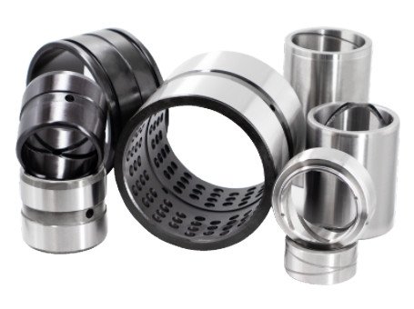
Gear sleeves are designed with specific structural characteristics to meet the demands of their applications. These features determine their functionality and compatibility with other components.
Gear-Like Profile: Gear sleeves typically have a toothed outer surface, similar to gears, which allows them to mesh with other gears or racks. This enables efficient power transmission and motion conversion. The tooth profile, such as involute or cycloidal, is designed to minimize wear and ensure smooth engagement.
Cylindrical Structure: The sleeve’s cylindrical shape includes an inner bore that fits onto a shaft, enabling rotation or axial movement. The bore is precision-machined to ensure a secure fit, often with tolerances of ±0.01 mm for high-performance applications.
Material Selection: Gear sleeves are commonly made from metals like alloy steel (e.g., AISI 4140), stainless steel, or bronze, chosen for their strength, hardness, and wear resistance. In applications requiring lightweight or noise-reducing properties, engineering plastics like nylon or polyacetal may be used. Material choice depends on factors such as load, speed, and environmental conditions.
| Feature | Description | Typical Specification |
|---|---|---|
| Tooth Profile | Involute or cycloidal for smooth meshing | Module 0.5–5 mm |
| Inner Bore Diameter | Fits shaft with tight tolerance | 10–100 mm |
| Wall Thickness | Balances strength and weight | 2–10 mm |
| Material Hardness | Ensures durability and wear resistance | 30–60 HRC (metal) |
Working Principles of Gear Sleeves
Gear sleeves operate by facilitating power transmission and motion control through their interaction with other components.
Power Transmission: Gear sleeves transmit torque by meshing their toothed surfaces with other gears or racks. For example, in a gear train, the sleeve on a driving gear engages a driven gear, transferring rotational motion and torque. This process relies on precise tooth geometry to ensure efficient power transfer with minimal energy loss.
Gear Shifting: In transmission systems, gear sleeves enable gear shifting by moving axially along a shaft to engage different gears. This changes the gear ratio, adjusting the output speed and torque. For instance, in an automotive gearbox, the sleeve slides to mesh with gears of varying tooth counts, adapting the vehicle’s performance to driving conditions.
Types of Gear Sleeves
Gear sleeves come in several types, each designed for specific applications and operational requirements.
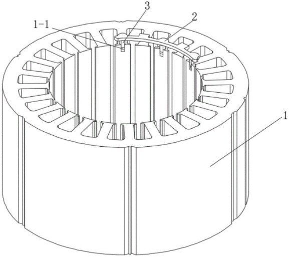
Synchronizer Sleeves: Used primarily in automotive transmissions, synchronizer sleeves ensure smooth gear shifts by synchronizing the rotational speeds of gears before engagement. They reduce shift shock and wear, improving driver comfort and component longevity.
Worm Gear Sleeves: These sleeves work with worm gears in reduction systems, enabling high gear ratios for converting high-speed rotation into low-speed, high-torque output. They are common in industrial machinery and elevators.
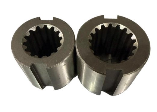
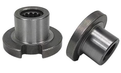
Spline Sleeves: Featuring internal spline grooves, these sleeves mate with splined shafts to transmit torque while allowing axial movement. They are used in applications like automotive driveshafts and machine tool feed systems, where high torque and sliding capability are required.
Material Selection and Properties
The choice of material for gear sleeves is critical to their performance. Common materials include:
- Alloy Steel (e.g., AISI 4140, 4340): Offers high strength (850–1000 MPa tensile strength) and hardness (50–55 HRC) for heavy-duty applications like automotive and industrial systems.
- Stainless Steel (e.g., 316): Provides corrosion resistance for marine or chemical processing environments, with moderate strength (500–700 MPa).
- Bronze (e.g., C93200): Used for low-friction applications, with tensile strength of 250–350 MPa, ideal for low-speed, high-contact scenarios.
- Engineering Plastics: Lightweight and noise-reducing, used in low-load applications like medical devices or consumer products.
Material selection considers factors like load capacity, wear resistance, and environmental exposure. For example, in high-temperature environments, materials with low thermal expansion coefficients are preferred to maintain fit.
Manufacturing Processes
Gear sleeves are manufactured using precision techniques to meet stringent tolerances. Common processes include:
- CNC Machining: Turning, milling, and grinding ensure precise dimensions and surface finishes (Ra 0.8–1.6 µm).
- Heat Treatment: Carburizing or induction hardening enhances surface hardness while maintaining core toughness.
- Surface Treatments: Nitriding or anti-friction coatings reduce wear and extend service life.
Quality control involves non-destructive testing (e.g., ultrasonic or magnetic particle inspection) and dimensional verification using coordinate measuring machines (CMM).
Performance Parameters
Key performance metrics for gear sleeves include:
- Torque Capacity: Ranges from 50 Nm to 5000 Nm, depending on material and geometry.
- Wear Rate: Typically below 0.1 mm per 1000 hours with proper lubrication.
- Fatigue Life: 10^6 to 10^7 cycles in cyclic loading conditions.
Lubrication, using oils (ISO VG 68–220) or greases, significantly impacts performance by reducing friction and wear.
Installation and Maintenance
Proper installation involves press-fitting or securing with set screws to prevent slippage. Alignment is verified using precision tools to avoid uneven loading. Maintenance includes regular inspections for wear, corrosion, or deformation, with lubrication applied per manufacturer specifications.
Limitations and Considerations
Gear sleeves face limitations such as thermal expansion, which can affect fit in high-temperature environments. Material compatibility with lubricants is critical to prevent degradation. Cost considerations arise with high-performance materials, requiring a balance between performance and budget. Improper installation can lead to misalignment or failure, emphasizing the need for skilled assembly.
Conclusion
Gear sleeves are vital for efficient power transmission and motion control across industries. Their design, material selection, and manufacturing must be optimized for specific applications. By understanding their structural features, working principles, and performance parameters, engineers can ensure reliable operation in demanding environments.