Impeller machining is a precision manufacturing process for creating rotating components used in pumps, turbines, and compressors to move fluids or gases. This guide details the machining process, types of impellers, and associated difficulties, focusing on technical aspects, specific parameters, and systematic approaches to achieve high-quality results.
Overview of Impeller Machining
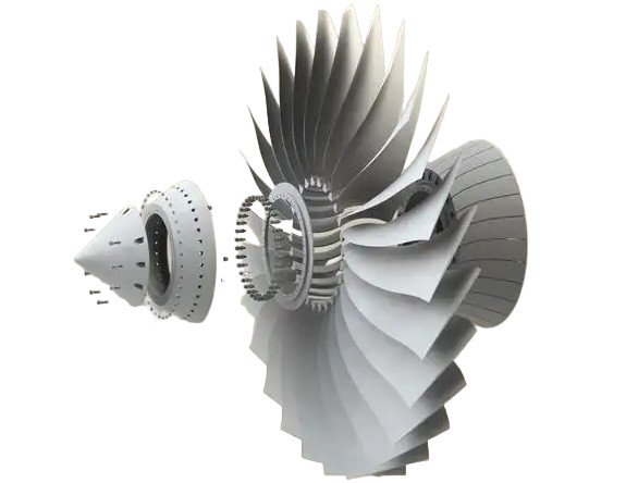
Impellers are critical components in fluid-handling systems, designed to transfer energy to fluids or gases. Machining impellers requires high precision due to their complex geometries, tight tolerances, and demanding performance requirements. The process involves material removal, surface finishing, and balancing to ensure efficiency and durability. Impellers are typically made from materials like stainless steel, aluminum, titanium, bronze, or high-performance plastics, selected based on application requirements such as corrosion resistance or weight.
The machining process uses advanced CNC (Computer Numerical Control) machines, often 5-axis systems, to handle intricate blade shapes and hub features. Key considerations include maintaining dimensional accuracy (e.g., tolerances of ±0.01 mm), achieving smooth surface finishes (e.g., Ra 0.8–1.6 µm), and ensuring dynamic balance to minimize vibration.
Types of Impellers
Impellers vary in design based on their application, flow characteristics, and structural requirements. The main types are outlined below, each with distinct machining considerations.
| Impeller Type | Description | Applications | Machining Considerations |
|---|---|---|---|
| Open Impeller | Blades are exposed without shrouds, allowing easy cleaning. | Pumps for slurries, wastewater treatment. | Simpler to machine; focus on blade edge precision (e.g., edge radius <0.1 mm). |
| Semi-Open Impeller | Blades attached to a single shroud, balancing efficiency and cleanability. | Chemical pumps, food processing. | Requires precise shroud-to-blade transitions; tolerances ±0.02 mm. |
| Closed Impeller | Blades enclosed between two shrouds, maximizing efficiency. | High-pressure pumps, turbines. | Complex 5-axis machining for internal channels; surface finish Ra 0.8 µm. |
| Mixed-Flow Impeller | Combines radial and axial flow for versatile performance. | HVAC systems, marine propulsion. | Requires precise blade curvature; machining angles up to 45°. |
Impeller Machining Process
The impeller machining process involves multiple stages, each requiring specific tools, techniques, and parameters to achieve the desired outcome. Below is a detailed breakdown of the process.
Design and Modeling
The process begins with designing the impeller using CAD (Computer-Aided Design) software like SolidWorks or CATIA. The design accounts for fluid dynamics, structural integrity, and application-specific requirements. CAM (Computer-Aided Manufacturing) software, such as Siemens NX or Fusion 360, generates toolpaths for CNC machines. Key parameters include blade thickness (e.g., 2–5 mm for pump impellers), hub diameter (e.g., 50–200 mm), and blade angles (e.g., 20–40° for optimal flow).
Material Selection and Preparation
Material choice depends on the impeller’s operating environment. For example, stainless steel (e.g., 316L) is used for corrosion resistance in water pumps, while titanium (e.g., Ti-6Al-4V) is chosen for aerospace applications due to its high strength-to-weight ratio. Raw material is prepared as a forging, casting, or bar stock, shaped to near-net dimensions to reduce machining time. For instance, a casting may have a dimensional allowance of 2–3 mm for finish machining.
Rough Machining
Rough machining removes bulk material to form the impeller’s basic shape. This is typically done using 3-axis or 5-axis CNC milling machines with high-speed steel (HSS) or carbide tools. Parameters include:
- Spindle speed: 5,000–15,000 RPM for aluminum, 1,000–3,000 RPM for titanium.
- Feed rate: 0.1–0.3 mm/rev for rough cuts.
- Depth of cut: 1–3 mm per pass.
The goal is to achieve a near-net shape within ±0.5 mm of final dimensions.
Finish Machining
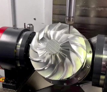
Finish machining refines the impeller to meet tight tolerances and surface finish requirements. 5-axis CNC machines are often used for complex blade profiles, ensuring accuracy in blade curvature and shroud geometry. Key parameters include:
- Surface finish: Ra 0.8–1.6 µm for hydraulic efficiency.
- Tolerances: ±0.01 mm for critical features like blade edges.
- Tool type: Ball-end mills (e.g., 6 mm diameter) for curved surfaces.
Grinding or polishing may be used for ultra-smooth finishes, especially in high-pressure applications.
Balancing
Dynamic balancing ensures the impeller operates without excessive vibration. Balancing machines measure imbalance (e.g., within 0.01 g·mm/kg) and guide material removal or addition. For example, material may be removed from heavier areas using drilling or milling, or weights may be added to lighter areas. Balancing is critical for high-speed impellers (e.g., 10,000–50,000 RPM).
Surface Treatment
Surface treatments enhance durability and performance. Polishing reduces surface roughness to Ra 0.4 µm or better, improving flow efficiency. Coatings like anodizing (for aluminum) or nitriding (for steel) improve corrosion resistance. Heat treatment may be applied to increase hardness (e.g., 30–40 HRC for stainless steel).
Inspection and Quality Control
Inspection verifies dimensional accuracy and surface quality. Coordinate Measuring Machines (CMM) measure tolerances to ±0.005 mm, while laser scanning checks blade profiles. Non-destructive testing, such as X-ray or ultrasonic inspection, detects internal defects. Surface roughness is measured using profilometers, targeting Ra 0.8–1.6 µm for most applications.
Difficulties in Impeller Machining
Impeller machining presents several technical difficulties due to the component’s complex geometry, material properties, and performance requirements. Below are key challenges:
Complex Geometry
Impellers often feature intricate blade shapes, such as twisted or curved profiles, requiring 5-axis CNC machines for simultaneous multi-axis machining. For closed impellers, internal channels are difficult to access, demanding specialized tools (e.g., long-reach end mills) and precise toolpath planning to avoid collisions. Blade thickness variations (e.g., 1–5 mm) require adaptive machining strategies to maintain uniformity.
Material Challenges
Materials like titanium and high-nickel alloys (e.g., Inconel) are difficult to machine due to their hardness (e.g., 30–45 HRC) and low thermal conductivity, leading to tool wear and heat buildup. For example, titanium requires low cutting speeds (e.g., 50–100 m/min) and high-pressure coolant (e.g., 70 bar) to prevent tool failure. Plastics, while easier to machine, risk deformation if excessive heat is generated.
Tight Tolerances
Impellers require tight tolerances (e.g., ±0.01 mm) to ensure hydraulic or aerodynamic performance. Maintaining these tolerances across complex surfaces is challenging, especially for large impellers (e.g., diameter >500 mm). Machine rigidity and tool deflection must be minimized, often requiring high-precision equipment and frequent calibration.
Surface Finish Requirements
Achieving smooth surface finishes (e.g., Ra 0.8 µm) is critical for efficiency but difficult on curved blade surfaces. Polishing complex geometries without altering dimensions is time-consuming and may require manual or robotic finishing systems. Inconsistent finishes can lead to flow losses or cavitation in pumps.
Balancing Precision
Dynamic balancing is critical but challenging, especially for high-speed impellers. Even minor imbalances (e.g., 0.02 g·mm/kg) can cause vibrations, reducing component life. Balancing requires precise measurement and material adjustment, which can be iterative and time-intensive.
Best Practices for Impeller Machining
To address these difficulties, manufacturers adopt several best practices:
| Practice | Description | Benefit |
|---|---|---|
| Advanced Toolpath Optimization | Use CAM software to optimize 5-axis toolpaths, minimizing tool deflection and vibration. | Improves accuracy and reduces machining time. |
| High-Performance Tools | Use carbide or diamond-coated tools for hard materials like titanium. | Extends tool life and maintains precision. |
| Coolant Management | Apply high-pressure coolant (e.g., 70–100 bar) to control heat and chip evacuation. | Reduces tool wear and improves surface finish. |
| In-Process Monitoring | Use sensors to monitor tool wear and machine vibration in real-time. | Prevents defects and ensures consistency. |
Conclusion
Impeller machining is a complex process requiring precision, advanced equipment, and careful planning. Understanding impeller types, mastering the machining process, and addressing difficulties like complex geometry and material challenges are essential for producing high-quality components. By adhering to best practices and leveraging advanced tools, manufacturers can achieve the tight tolerances, smooth finishes, and balanced performance required for impellers in critical applications.