Locating pins are essential mechanical components used for precise alignment, securing, or positioning of two or more parts in manufacturing, tooling, and automation systems. By engaging with corresponding holes or slots, they restrict relative movement or rotation, ensuring assembly accuracy and stability. This article explores the characteristics, types, materials, specifications, applications, and design considerations of locating pins, providing a technical and systematic resource for engineers and professionals.
Definition and Function of Locating Pins
Locating pins are precision-engineered components designed to align and fix parts in a specific position during manufacturing, assembly, or inspection processes. They fit into precisely machined holes or bushings in workpieces or fixtures, limiting movement in specific directions to maintain dimensional accuracy. Their primary function is to ensure repeatability and stability, making them indispensable in industries requiring tight tolerances, such as automotive, aerospace, and mold manufacturing.
Locating pins achieve high precision by restricting degrees of freedom (e.g., translation or rotation) between components. They are typically used in pairs or sets to provide robust positioning while accommodating minor manufacturing variations.
Key Characteristics of Locating Pins
Locating pins are designed with specific features to meet the demands of precision engineering. These characteristics include:
- High Precision: Manufactured from high-hardness materials such as tool steel or stainless steel, locating pins undergo precision grinding to achieve tight dimensional tolerances (e.g., diameter tolerances of ±0.005 mm to ±0.01 mm) and excellent surface finish (e.g., Ra 0.2–0.8 µm).
- Durability: Heat-treated or coated to resist wear, corrosion, and deformation under load.
- Versatility: Available in various shapes and sizes to suit different applications, from general-purpose to high-precision tasks.
- Ease of Use: Designed for easy insertion and removal, especially in applications requiring frequent setup changes.
Types of Locating Pins
Locating pins are available in several configurations, each tailored to specific positioning requirements. The following are the most common types, with their features and applications.
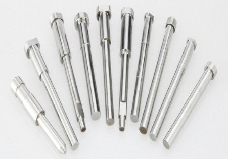
Cylindrical Pins
Cylindrical pins have a uniform diameter and are used for general-purpose positioning. They rely on clearance fits (e.g., H7/g6) or interference fits (e.g., H7/r6) to align components in two dimensions (X and Y axes). These pins are cost-effective and widely used in applications with moderate precision requirements, such as fixture alignment in machining.
Tapered Pins
Tapered pins feature a conical shape with a standard taper ratio (typically 1:50). The tapered design provides a self-locking mechanism through wedging action, ensuring high positioning accuracy and ease of insertion/removal. They are ideal for applications requiring frequent disassembly, such as mold alignment in injection molding.
Diamond Pins
Diamond pins have a diamond-shaped cross-section, which restricts rotation in one direction while allowing clearance in another. Often used in conjunction with cylindrical pins, they prevent over-constraint and accommodate minor misalignments due to machining tolerances. They are common in precision fixtures and jigs.
Locating Pin Bushings
Locating pin bushings are complementary components that protect the mating hole from wear and extend the lifespan of the fixture or workpiece. Made from hardened steel or other durable materials, bushings ensure a precise fit with the pin and are replaceable to maintain accuracy over time.
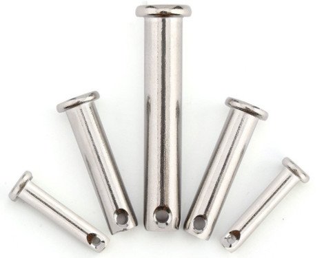
Shoulder Pins
Shoulder pins include a larger-diameter shoulder that acts as a stop to control insertion depth. They are used in applications requiring precise vertical positioning (Z-axis), such as stacked assemblies or fixtures with height constraints.
Materials and Specifications
The choice of material for locating pins depends on the application’s load, environmental conditions, and precision requirements. Common materials and their properties are outlined below:
| Material | Properties | Applications |
|---|---|---|
| Tool Steel (e.g., AISI D2) | High hardness (58–62 HRC), wear resistance | High-load, precision machining |
| Stainless Steel (e.g., 304, 316) | Corrosion resistance, moderate hardness | Food processing, medical equipment |
| Titanium Alloy (e.g., Ti-6Al-4V) | High strength-to-weight ratio, corrosion resistance, moderate hardness (30–36 HRC) | Aerospace, medical, lightweight applications |
| Carbide | Extreme hardness (up to 90 HRC), wear resistance | High-precision, abrasive environments |
| Ceramic | Non-magnetic, high temperature resistance | Electronics, high-temperature applications |
Typical specifications for locating pins include:
| Parameter | Range | Description |
|---|---|---|
| Diameter | 1 mm to 25 mm | Nominal diameter, with tolerances of ±0.005 mm to ±0.01 mm |
| Length | 5 mm to 100 mm | Total length, including shoulder or head |
| Tolerance | H6, H7, or custom | ISO tolerance for precise fit with mating holes |
| Surface Finish | Ra 0.2–0.8 µm | Ensures smooth insertion and minimal wear |
Applications of Locating Pins
Locating pins are used in various industries to ensure precise alignment and stability. Key applications include:
Mechanical Assembly
In mechanical assemblies, such as those in automotive or machinery manufacturing, locating pins align components like engine parts or chassis panels. They ensure coaxiality and parallelism, reducing assembly errors and improving product quality.
Mold Industry
In injection molding and stamping dies, locating pins align upper and lower mold halves to prevent misalignment, which could lead to defective parts. Tapered pins are often used for their ease of removal during mold maintenance.
Automation Equipment
In automated production lines, locating pins facilitate rapid workpiece positioning in jigs and fixtures, enhancing throughput. They are critical in high-speed assembly or robotic systems where repeatability is paramount.
Inspection and Quality Control
Locating pins secure workpieces during inspection, ensuring consistent positioning for accurate measurements with tools like coordinate measuring machines (CMM).
Design Considerations for Locating Pins
Effective use of locating pins requires careful design to ensure performance and reliability. Key considerations include:
Fit and Tolerance
The fit between the pin and mating hole is critical. Common fits include:
- H7/g6 (Clearance Fit): Allows easy insertion with minimal play, suitable for general applications.
- H7/r6 (Interference Fit): Provides a tight, secure fit for high-precision or high-load applications.
Tolerance selection depends on the application’s precision requirements and the expected machining accuracy of the mating hole.
Pin Layout
A typical configuration uses two pins: one cylindrical to constrain translation (X and Y axes) and one diamond to restrict rotation. This setup prevents over-constraint while accommodating minor machining errors.
Strength and Load Capacity
Pins must withstand shear and bending forces without deforming. The pin diameter and material are selected based on the expected load. For example, a 10 mm diameter tool steel pin can typically handle shear forces up to 50 kN, depending on the material’s yield strength.
Environmental Factors
Environmental conditions, such as exposure to moisture, chemicals, or high temperatures, influence material choice. Stainless steel or ceramic pins are preferred in corrosive or high-temperature environments.
Common Issues and Solutions
While locating pins are reliable, certain issues can affect their performance. Below are common problems and their solutions:
Misalignment
Misalignment occurs when the pin and hole are not perfectly matched, causing binding or inaccurate positioning. Using tapered or diamond pins can accommodate slight misalignments, while improving hole machining precision (e.g., reaming to H7 tolerance) resolves the issue.
Wear and Damage
Frequent insertion/removal or abrasive conditions can cause pin wear or deformation. Selecting wear-resistant materials (e.g., carbide) or using bushings to protect mating holes extends service life. Regular inspection and replacement are recommended.
Over-Constraint
Using multiple cylindrical pins can over-constrain the system, leading to assembly difficulties. Combining a cylindrical pin with a diamond pin prevents over-constraint while maintaining precision.
Installation and Maintenance
Proper installation and maintenance ensure long-term performance. Installation involves pressing or screwing the pin into the fixture, ensuring alignment with the mating hole. Maintenance includes:
- Inspecting pins for wear, such as rounding or scoring, using precision tools like micrometers.
- Cleaning pins and bushings to remove debris or contaminants.
- Replacing worn pins or bushings to maintain dimensional accuracy.
Conclusion
Locating pins are small but critical components in precision engineering, ensuring accurate alignment and stability in mechanical assemblies, molds, and automation systems. By understanding their types, materials, specifications, and design considerations, engineers can select and implement locating pins effectively. Addressing common issues like misalignment or wear through proper design and maintenance enhances reliability and performance. This guide serves as a comprehensive resource for professionals seeking to optimize the use of locating pins in their applications.