Surface roughness detection is a critical technique for evaluating micro-irregularities on a surface, widely applied in mechanical manufacturing, automotive, aerospace, and other industries. It directly influences properties such as wear resistance, sealing performance, and mating precision. This article provides a detailed, technical exploration of surface roughness detection, including its principles, methods, equipment, operational procedures, and applications, ensuring clarity and systematic coverage for professionals.
Fundamentals of Surface Roughness
Surface roughness refers to the micro-geometric features of a machined surface, characterized by small-scale peaks and valleys. These features are quantified using standardized parameters, primarily defined by ISO 4287:1997 and GB/T 1031-2009, such as:
- Ra (Arithmetic Average Roughness): The arithmetic mean of the absolute deviations of the surface profile within a sampling length. Ra is the most commonly used parameter, typically ranging from 0.025 to 6.3 µm.
- Rz (Maximum Height of Profile): The average of the sum of the maximum peak height and maximum valley depth within a sampling length, often ranging from 0.1 to 50 µm.
- Rq (Root Mean Square Roughness): The square root of the arithmetic mean of squared profile deviations, more sensitive to peak variations, typically 0.1 to 10 µm.
These parameters provide a quantitative basis for assessing surface quality and its impact on performance metrics like friction and durability.
Common Surface Roughness Detection Methods
Surface roughness detection methods are broadly classified into contact and non-contact techniques, each suited to specific applications based on precision, material properties, and operational constraints.
Contact-Based Detection Methods
Contact methods involve physical interaction with the surface, typically using a probe to measure micro-irregularities.
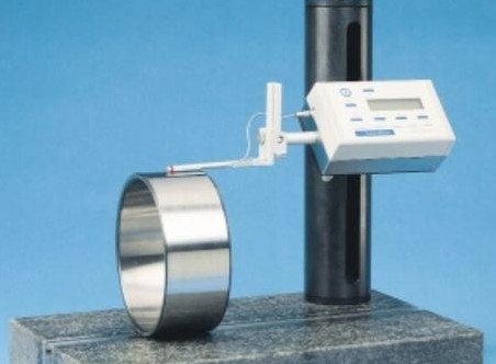
Stylus Profilometry
Stylus profilometry employs a diamond-tipped stylus (tip radius 2–10 µm) that slides across the surface, detecting vertical displacements converted into electrical signals via sensors (e.g., inductive or piezoelectric). The system processes these signals to calculate roughness parameters like Ra, Rz, and Rq.
Parameters:
- Tip Radius: 2–10 µm, influencing measurement resolution.
- Scanning Speed: 0.5–1 mm/s, ensuring accuracy without vibration.
- Sampling Length: 0.8–8 mm, typically 0.8 mm for fine surfaces and 2.5 mm for rougher surfaces.
- Measurement Range: Ra 0.025–6.3 µm, suitable for most machined surfaces.
Applications: Precision metal components, such as engine shafts and molds, in automotive and manufacturing industries.
Limitations: Potential micro-scratches on soft materials (e.g., aluminum, plastics), slow measurement speed, and limited to 2D profiles.
Surface Comparison Method
This method compares the test surface with standard roughness specimens (e.g., sandblasted, turned, or ground samples) using visual inspection (with a magnifying glass or microscope) or tactile assessment.
Features: Simple and low-cost but less accurate, relying on operator experience for qualitative or semi-quantitative results.
Applications: Quick inspections in workshops where high precision is not required.
Non-Contact Detection Methods
Non-contact methods use optical or imaging technologies, ideal for delicate or complex surfaces, avoiding damage and enabling 3D analysis.
Optical Interferometry
Optical interferometry, such as Michelson interferometry, measures surface roughness by analyzing interference patterns formed by reflected light from the test surface and a reference plane. The degree of fringe distortion correlates with surface topography.
Parameters:
- Resolution: Nanometer-scale vertical resolution (e.g., 1 nm).
- Scan Area: Typically 100 µm × 100 µm to 1 mm × 1 mm.
- Measurement Time: 5–20 seconds per scan.
Applications: Ultra-precision surfaces, such as semiconductor chips and optical lenses.
Limitations: Sensitivity to reflective surfaces and environmental vibrations.
Laser Confocal Microscopy
Laser confocal scanning microscopy (CLSM) uses a focused laser beam to scan the surface, capturing reflected light to construct 3D topography. Systems like the Olympus Lext OLS 3100 achieve high resolution for detailed analysis.
Parameters:
- Lateral Resolution: 0.1 µm.
- Vertical Resolution: 0.01 µm.
- Laser Wavelength: 405 nm for high contrast.
- Scan Area: Up to 129 µm × 96 µm at 100× magnification.
Applications: Complex surfaces, micro-components, and 3D-printed parts.
Machine Vision
Machine vision captures surface images with high-resolution cameras, using algorithms (e.g., grayscale analysis, texture recognition) to extract roughness features compared against a standard database.
Features: Fast, suitable for automated in-line inspection, but accuracy depends on lighting and image quality.
Applications: Mass production lines for automotive parts and electronics.
Selection of Detection Equipment
Choosing the appropriate method and equipment depends on the surface type, precision requirements, and operational context. The following table summarizes recommendations:
| Detection Need | Recommended Method/Equipment | Advantages |
|---|---|---|
| High Precision, Hard Surfaces | Stylus Profilometer | High accuracy, comprehensive parameters |
| Ultra-Precision (Nanoscale) | Optical Interferometer, CLSM | Non-contact, nanoscale resolution |
| Rapid Qualitative Inspection | Comparison Method | Simple, low-cost |
| In-Line Batch Testing | Machine Vision | Automated, fast |
| Soft/Delicate Surfaces | CLSM, Optical Interferometry | Non-contact, no damage |
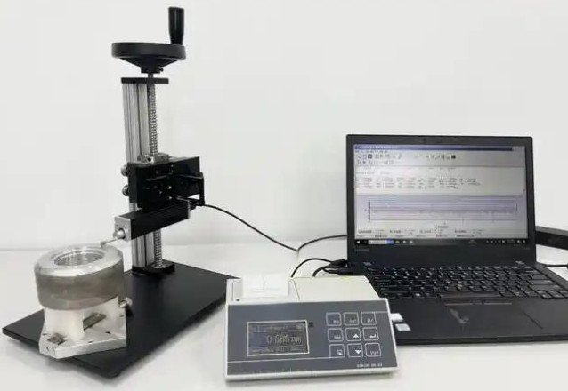
Operational Procedure (Stylus Profilometry Example)
The following steps outline the process for using a stylus profilometer, ensuring repeatable and accurate measurements:
- Sample Preparation: Clean the surface with alcohol to remove oil, dust, or contaminants, ensuring a dry surface.
- Instrument Calibration: Use a standard roughness block (e.g., Ra = 0.8 µm) to calibrate the stylus and sensor.
- Parameter Setup: Select sampling length (0.8 mm for fine surfaces, 2.5 mm for rougher surfaces), evaluation length (typically 5× sampling length), and parameters (Ra, Rz, etc.).
- Measurement Execution: Gently place the stylus on the surface, scan perpendicular to surface texture (e.g., radially for turned surfaces), and avoid edge effects.
- Data Processing: The instrument calculates and displays roughness parameters, which can be exported as numerical data or graphs.
- Repeat Measurements: Perform 3–5 measurements at different locations, averaging results to minimize errors.
Key Considerations
Environmental Control: Minimize vibrations (e.g., from nearby machinery), temperature fluctuations (affecting instrument precision), and strong light interference (for non-contact methods).
Surface Condition: Ensure surfaces are flat and free of macroscopic defects like scratches or pores, which can skew results.
Stylus Protection: Handle precision styluses carefully to avoid damage or wear, replacing them periodically.
Standards Compliance: Adhere to standards like GB/T 1031-2009 or ISO 4287 for consistent, comparable results.
Applications in Industry
Surface roughness detection is vital for ensuring product quality across various sectors:
Mechanical Manufacturing
Roughness of mating surfaces (e.g., shafts, bearings) affects transmission accuracy and lifespan. Typical Ra values range from 0.8 to 3.2 µm for functional surfaces.
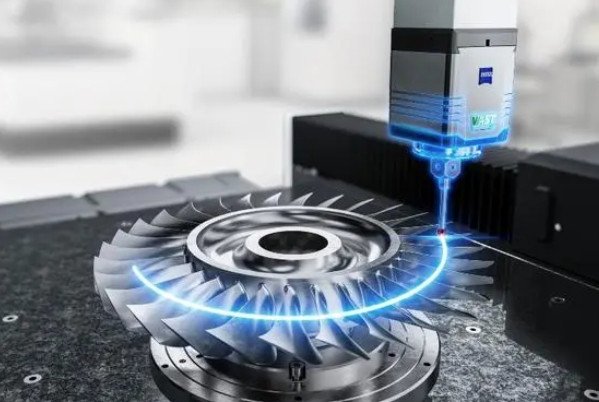
Aerospace
Engine blades and sealing surfaces require low roughness (Ra < 0.5 µm) to reduce airflow resistance and leakage risks, often measured with CLSM.
Electronics
Surface roughness of chip bonding areas (Ra < 0.1 µm) impacts welding strength, while circuit board roughness affects coating adhesion, typically measured with optical interferometry.
Medical Devices
Artificial joints require low roughness (Ra < 0.4 µm) to minimize wear and tissue reactions, using non-contact methods to avoid contamination.
Conclusion
Surface roughness detection is essential for ensuring product performance and reliability in manufacturing. Contact methods like stylus profilometry offer high accuracy for robust surfaces, while non-contact methods like optical interferometry and CLSM excel in precision and delicate applications. By selecting appropriate methods, equipment, and procedures, and adhering to standards, industries can effectively control surface quality to meet stringent performance requirements.