This guide provides a comprehensive overview of turbine blades, focusing on their types, design, materials, manufacturing processes, and maintenance practices. Turbine blades are critical components in gas turbines, steam turbines, and wind turbines, converting fluid or air energy into mechanical work. The content is structured to deliver technical, professional, and systematic information for engineers, technicians, and industry professionals seeking detailed insights into turbine blade functionality and management.
Overview of Turbine Blades
Turbine blades are aerodynamic components designed to extract energy from a moving fluid or gas. In gas turbines, they operate under high temperatures and pressures, while in wind turbines, they harness kinetic energy from air. Their performance directly impacts the efficiency, reliability, and lifespan of the turbine system. This section outlines their role, types, and key considerations.
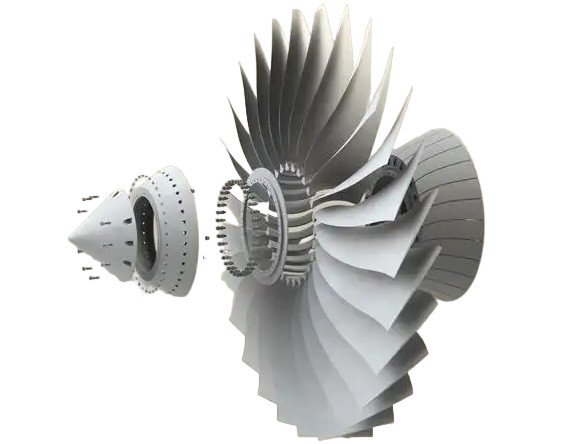
Blades are typically found in the turbine’s rotor or stator sections. Rotor blades rotate to produce mechanical energy, while stator blades (vanes) direct fluid flow to optimize energy transfer. The design must balance aerodynamic efficiency, structural integrity, and thermal resistance, especially in high-temperature environments like gas turbines.
Types of Turbine Blades
Blades are categorized based on turbine type, working principle, and location within the turbine:
By Turbine Type
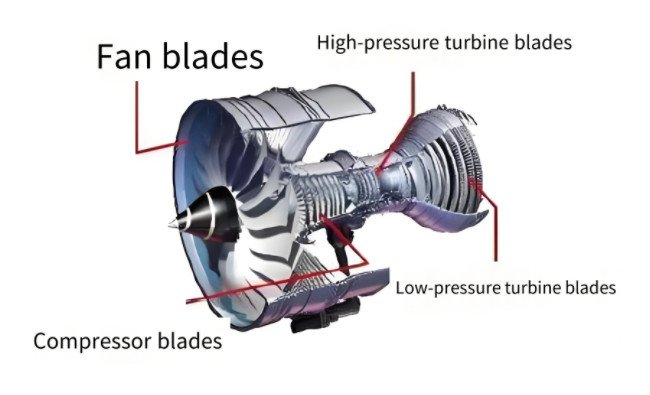
- Gas Turbine Blades: Operate in high-temperature (up to 1,600°C) and high-pressure environments. They are divided into:
- Compressor Blades: Located in the turbine’s compressor section, compressing incoming air (not directly exposed to combustion gases).
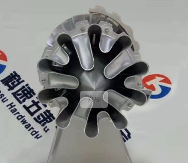
- Turbine Blades: In the turbine section, exposed to hot combustion gases; require advanced cooling systems (e.g., internal air channels).
- Steam Turbine Blades: Designed for high-pressure steam (300–650°C). Classified as:
- Impulse Blades: Converted steam kinetic energy into mechanical work via impact (steam expands in nozzles, not in blades).
- Reaction Blades: Steam expands both in nozzles and blades, generating thrust from pressure differences across the blade.
- Wind Turbine Blades: Large, lightweight blades (up to 100+ meters) that capture wind energy. Shaped for low-speed efficiency (10–30 rpm) and flexibility to withstand gusts.
- Hydraulic Turbine Blades: Used in water turbines (e.g., Francis, Kaplan turbines), designed to harness water flow. Materials focus on corrosion resistance (e.g., stainless steel).
By Position in the Turbine
- Stage 1 (High-Pressure) Blades: Exposed to the highest temperatures/pressures (e.g., in gas turbines, first-stage blades face combustion gases directly).
- Later-Stage Blades: Operate in lower-temperature/pressure environments but may be longer to extract remaining fluid energy.
Turbine Blade Design Parameters
The design of turbine blades involves precise engineering to meet operational demands. Key parameters include blade geometry, aerodynamic profiles, and structural considerations. The following table summarizes critical design parameters:
| Parameter | Description | Typical Values |
|---|---|---|
| Blade Length | Determines the blade’s ability to capture energy | 0.5–2 m (gas turbines), 20–80 m (wind turbines) |
| Chord Length | Width of the blade’s cross-section | 0.1–0.5 m (gas turbines), 1–5 m (wind turbines) |
| Twist Angle | Angle variation along the blade for aerodynamic efficiency | 0–30° (wind turbines) |
| Camber | Curvature of the blade’s airfoil shape | 2–10% of chord length |
| Tip Speed Ratio | Ratio of blade tip speed to fluid speed | 6–8 (wind turbines), 1–2 (gas turbines) |
Blade geometry is optimized using computational fluid dynamics (CFD) to minimize drag and maximize lift. For gas turbines, the blade profile must withstand centrifugal forces and thermal stresses, often requiring cooling channels to manage temperatures exceeding 1500°C. Wind turbine blades prioritize lightweight construction and aerodynamic efficiency to optimize energy capture at varying wind speeds.
Materials Used in Turbine Blades
Material selection is critical due to the extreme operating conditions of turbine blades. The choice depends on factors such as temperature, mechanical stress, and corrosion resistance. Common materials include:
- Nickel-Based Superalloys: Used in gas turbines for their high-temperature strength and creep resistance. Common alloys include Inconel 718 and René 41, with melting points above 1300°C and tensile strengths of 800–1200 MPa.
- Titanium Alloys: Employed in compressor blades for their high strength-to-weight ratio and corrosion resistance. Ti-6Al-4V is a common choice, with a density of 4.43 g/cm³ and yield strength of 880 MPa.
- Composite Materials: Wind turbine blades often use glass fiber reinforced polymers (GFRP) or carbon fiber reinforced polymers (CFRP) for their lightweight properties and fatigue resistance. GFRP has a density of 1.8–2.0 g/cm³, while CFRP is lighter at 1.5–1.6 g/cm³.
- Ceramic Matrix Composites (CMCs): Emerging in gas turbines for their ability to withstand temperatures up to 1700°C with lower cooling requirements compared to superalloys.
Coatings, such as thermal barrier coatings (TBCs) made of yttria-stabilized zirconia, are applied to gas turbine blades to enhance thermal resistance. These coatings can reduce surface temperatures by 100–300°C, extending blade life.
Manufacturing Processes for Turbine Blades
Manufacturing turbine blades requires precision to achieve complex geometries and material properties. The primary methods include:
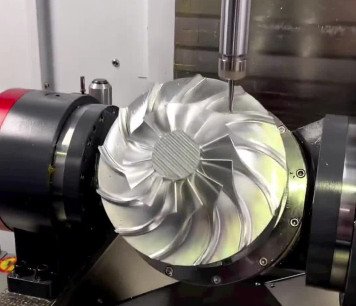
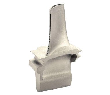
- Investment Casting: Used for gas turbine blades, this process involves creating a wax model, coating it with ceramic, and pouring molten metal. It allows for intricate cooling channels with tolerances as low as ±0.05 mm.
- Directionally Solidified (DS) Casting: Produces blades with aligned grain structures to enhance creep resistance. This is common for high-temperature applications, achieving grain alignment within 5° of the blade axis.
- Single Crystal Casting: Eliminates grain boundaries to improve thermal and mechanical performance. Single-crystal blades can operate at temperatures 50–100°C higher than polycrystalline blades.
- Composite Lay-Up: For wind turbine blades, layers of fiberglass or carbon fiber are laid in molds and infused with resin. This process achieves blade lengths up to 80 m with a surface finish roughness of Ra 1.6 µm.
- Additive Manufacturing: Emerging for prototyping and complex geometries, with layer thicknesses of 20–100 µm, though it is not yet widely used for production blades.
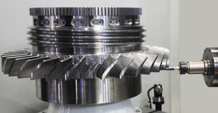
Post-processing, such as machining and polishing, ensures dimensional accuracy and surface quality. For gas turbine blades, cooling holes are drilled using laser or electrical discharge machining (EDM) with diameters of 0.3–1 mm.
Maintenance and Inspection of Turbine Blades
Regular maintenance and inspection are essential to ensure turbine blade performance and longevity. Key practices include:
- Non-Destructive Testing (NDT): Techniques like ultrasonic testing and X-ray inspection detect internal defects such as cracks or voids. Ultrasonic testing can identify flaws as small as 0.1 mm.
- Thermal Imaging: Used to assess coating integrity and detect hot spots, with temperature resolution of 0.1°C.
- Visual Inspection: Conducted using borescopes for gas turbines or drones for wind turbines to identify surface damage like erosion or pitting.
- Coating Reapplication: Thermal barrier coatings are reapplied after 20,000–30,000 operating hours to restore thermal protection.
- Blade Replacement: Blades are replaced based on fatigue life, typically after 100,000 hours for gas turbines or 20–25 years for wind turbines.
Maintenance schedules depend on operating conditions. For example, gas turbine blades in baseload power plants require inspection every 8,000–12,000 hours, while wind turbine blades are inspected annually or after extreme weather events.
Performance Optimization Techniques
Optimizing turbine blade performance involves improving efficiency and durability. Key techniques include:
- Aerodynamic Optimization: Adjusting blade twist and camber to reduce drag. CFD simulations can improve efficiency by 1–2%.
- Cooling Systems: Gas turbine blades use internal cooling channels and film cooling to manage temperatures. Cooling air flow rates are typically 2–5% of the main gas flow.
- Surface Treatments: Polishing reduces surface roughness to Ra 0.8 µm, minimizing drag and improving efficiency.
- Load Monitoring: Sensors embedded in wind turbine blades monitor strain and fatigue, with strain gauges detecting deformations as small as 1 microstrain.
These techniques are tailored to the turbine type and operating environment, ensuring maximum energy output and component longevity.
Environmental and Operational Considerations
Turbine blades must withstand environmental and operational stresses. Gas turbine blades face high temperatures (up to 1600°C) and pressures (10–30 bar), requiring robust materials and cooling systems. Wind turbine blades endure cyclic loading from wind gusts, with fatigue cycles exceeding 10^8 over their lifespan. Environmental factors, such as saltwater corrosion for offshore wind turbines, necessitate protective coatings with thicknesses of 200–500 µm.
Operational considerations include matching blade design to specific conditions, such as low wind speeds (3–5 m/s) for wind turbines or high-altitude operations for gas turbines, where air density is 10–20% lower.
Case Studies of Turbine Blade Applications
Practical applications highlight the importance of design and maintenance:
- Gas Turbine Power Plant: A 500 MW combined-cycle plant uses single-crystal nickel-based superalloy blades with TBCs, achieving a thermal efficiency of 60%. Regular NDT every 10,000 hours ensures reliability.
- Offshore Wind Farm: A 100 MW wind farm employs 60 m CFRP blades with a twist angle of 15°. Annual drone inspections and UV-resistant coatings extend blade life to 25 years.
These examples demonstrate the application of design principles and maintenance strategies in real-world scenarios.
Summary of Key Parameters
| Aspect | Gas Turbine Blades | Wind Turbine Blades |
|---|---|---|
| Material | Nickel-based superalloys, CMCs | GFRP, CFRP |
| Operating Temperature | Up to 1600°C | -20°C to 50°C |
| Lifespan | 100,000 hours | 20–25 years |
| Inspection Frequency | Every 8,000–12,000 hours | Annually |
Conclusion
Turbine blades are engineered with precision to meet demanding operational requirements. By understanding their types, design parameters, material properties, manufacturing techniques, and maintenance practices, professionals can ensure optimal performance and longevity. This guide provides a systematic framework for addressing the complexities of turbine blade management, offering actionable insights for engineers and technicians.