The turbine rotor is a pivotal component in turbomachinery, converting the kinetic and thermal energy of fluids—such as gas, steam, or air—into mechanical rotational motion to drive generators, compressors, or other equipment. Its design, material selection, and performance directly influence the efficiency, reliability, and lifespan of turbines used in applications like power generation, aviation, and renewable energy. This guide provides a detailed exploration of turbine rotors, focusing on their structure, design principles, materials, performance characteristics, and maintenance considerations, with specific parameters to ensure technical accuracy.
Overview of Turbine Rotors
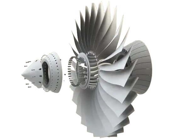
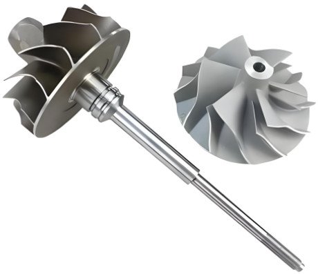
A turbine rotor is the rotating assembly within a turbine, comprising a shaft or drum, blades, and associated components like couplings and seals. It extracts energy from a fluid and converts it into rotational energy. Turbine rotors are integral to various systems, including gas turbines for aviation and industrial power, steam turbines for electricity generation, and wind turbines for renewable energy. The rotor’s design must ensure structural integrity, aerodynamic efficiency, and operational stability under diverse conditions.
Key functions include:
- Converting fluid energy into mechanical work.
- Transmitting rotational energy to external systems.
- Maintaining stability under high speeds, temperatures, and loads.
Basic Components of Turbine Rotors
Turbine rotors consist of several critical components, each designed to withstand specific mechanical and thermal loads. These components vary slightly depending on the turbine type but generally include:
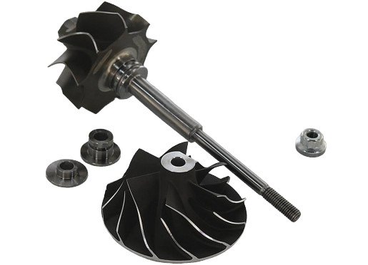
Rotor Discs
Rotor discs anchor the blades and transfer centrifugal and aerodynamic loads to the shaft. They are typically made from high-strength alloys, such as forged steel or nickel-based superalloys, to withstand forces exceeding 10,000 g in high-speed turbines. Discs are designed with precise tolerances (e.g., 0.01 mm) to ensure balance and minimize vibration.
Blades
Blades interact directly with the fluid, extracting energy through impulse or reaction mechanisms. Blade geometry—chord length (50–300 mm), twist angle (0–30°), and airfoil shape—is optimized for aerodynamic efficiency. For example, gas turbine blades use complex airfoil profiles to handle supersonic flows, while wind turbine blades prioritize low-speed aerodynamics.
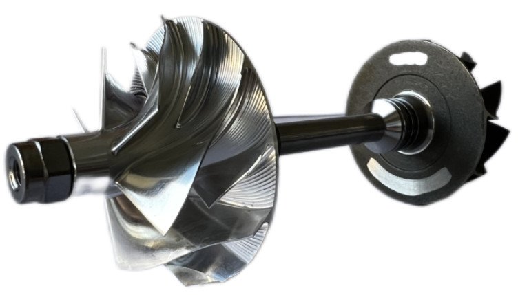
Shaft
The shaft transmits torque to external equipment, such as generators or compressors. It requires high stiffness (Young’s modulus >200 GPa for steel) and fatigue resistance to endure cyclic loads. Shafts are often forged from a single piece to eliminate weak points, with diameters ranging from 0.1 m in small gas turbines to 1 m in large steam turbines.
Couplings
Couplings connect the rotor to other components, compensating for misalignment (typically <0.05 mm). Flexible couplings, such as gear or diaphragm types, are used to reduce stress transmission. Torque capacities range from 10 kN·m in small turbines to over 500 kN·m in large steam turbines.
Seals
Seals minimize fluid leakage, improving efficiency. Labyrinth seals, with clearances of 0.1–0.5 mm, are common in gas and steam turbines, while brush seals reduce leakage by 10–20% in high-pressure applications. Seal design must balance leakage reduction with frictional losses.
Types and Applications of Turbine Rotors
Turbine rotors are tailored to specific applications, with designs reflecting the operating environment and fluid dynamics. The following outlines the main types and their applications:
Gas Turbine Rotors
Used in aviation (jet engines) and industrial power generation, gas turbine rotors operate at high temperatures (800–1,100°C) and speeds (10,000–30,000 rpm). They are typically axial-flow designs with multiple blade stages. Materials like nickel-based superalloys (e.g., Inconel 718) resist creep and oxidation, with cooling channels reducing blade temperatures by 200–300°C.
Steam Turbine Rotors
Steam turbine rotors, used in fossil fuel and nuclear power plants, operate at 300–650°C and 1,800–3,600 rpm. They are designed as impulse or reaction types, with mono-block (single forging) or built-up (assembled discs) configurations. Forged steel (e.g., 12% Cr-Mo-V) provides strength and cost-effectiveness.
Wind Turbine Rotors
Wind turbine rotors capture wind energy at low speeds (10–30 rpm) with large blade diameters (70–107 m). Blades are made from lightweight composites like fiberglass or carbon fiber, with lengths up to 52 m for 12 MW turbines. The rotor must withstand dynamic loads from gusts and turbulence.
Water Turbine Rotors
Water turbine rotors, used in hydroelectric power, are driven by water flow in impulse (Pelton) or reaction (Francis, Kaplan) designs. Materials like stainless steel resist corrosion, with rotor diameters ranging from 1–10 m depending on power output (10 MW–1 GW).
Design Principles and Technical Requirements
Turbine rotor design involves balancing aerodynamic performance, structural integrity, and thermal management. Key considerations include mechanical strength, thermal resilience, and dynamic stability.
Mechanical Performance
Rotors endure centrifugal forces (proportional to ρr²ω²), thermal stresses from temperature gradients (up to 1,000°C in gas turbines), and aerodynamic loads (10–100 kN per blade). Materials must have high yield strength (600–1,200 MPa) and toughness to prevent failure. For example, a gas turbine rotor at 15,000 rpm with a 0.5 m radius experiences centrifugal stresses of 500–800 MPa.
Thermal Management
High-temperature environments, particularly in gas turbines, require cooling systems. Internal cooling passages (1–3 mm diameter) circulate air, reducing blade temperatures by 200–300°C. Thermal barrier coatings (e.g., yttria-stabilized zirconia) extend blade life by 20–30%. Steam turbines use insulation and staged steam expansion to manage temperatures below 650°C.
Dynamic Stability
Rotors must avoid resonance, where the critical speed aligns with the operating speed. Modal analysis ensures the critical speed is below the operating range (e.g., <3,000 rpm for a 3,600 rpm turbine). Vibration amplitudes are kept below 0.1 mm, monitored by non-contact sensors like fiber Bragg grating (FBG) systems.
Lifespan and Reliability
Rotors are designed for 10,000–30,000 cycles in gas turbines and up to 100,000 hours in steam turbines. Fatigue cracks, corrosion, and wear are mitigated through rounded transitions (radii >2 mm) to reduce stress concentrations and regular non-destructive testing (NDT), such as ultrasonic or eddy current methods.
Material Selection
Material choice is driven by operating conditions, balancing strength, weight, and cost. The following table summarizes common materials and their properties:
| Material | Turbine Type | Yield Strength (MPa) | Operating Temp (°C) | Key Characteristics |
|---|---|---|---|---|
| Nickel-Based Superalloys (e.g., Inconel 718) | Gas Turbine | 800–1,200 | Up to 1,100 | Creep and oxidation resistance |
| High-Strength Steel (e.g., 12% Cr-Mo-V) | Steam Turbine | 600–900 | Up to 650 | Fatigue strength, cost-effective |
| Fiberglass/Carbon Fiber Composites | Wind Turbine | 300–500 | Ambient | Lightweight, corrosion-resistant |
| Stainless Steel | Water Turbine | 500–800 | Ambient | Corrosion resistance, durability |
Ceramic matrix composites (CMCs) are emerging for ultra-high-temperature applications, offering 20–30% weight reduction and improved thermal resistance over superalloys.
Performance Characteristics
Rotor performance is evaluated through efficiency, power output, and durability, with parameters varying by turbine type.
Efficiency Metrics
Isentropic efficiency measures the rotor’s ability to convert fluid energy into work. Typical values are 85–90% for gas turbines, 80–85% for steam turbines, and a power coefficient (Cp) of 0.4–0.5 for wind turbines (Betz limit: 0.59). Efficiency is enhanced by optimizing blade profiles and minimizing tip clearances (e.g., 0.5–1 mm in gas turbines).
Power Output and Torque
Power output (P = τω) depends on torque (τ) and angular velocity (ω). For a 1 MW wind turbine (70 m diameter, 12 m/s wind speed), torque is ~318 kN·m at 20 rpm. Gas turbines produce 50–500 MW with torques of 10–50 kN·m at 3,000–15,000 rpm.
Durability
Fatigue life is critical, with gas turbine rotors designed for 10,000–30,000 cycles and steam turbines for 100,000 hours. Environmental factors, like corrosion in water turbines or oxidation in gas turbines, are mitigated through material selection and coatings.
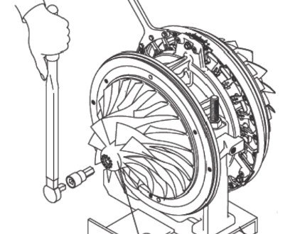
Maintenance and Fault Diagnosis
Regular maintenance ensures rotor reliability and extends lifespan. Common issues and solutions include:
Common Faults
Typical faults include blade wear or fracture, disc cracks, shaft misalignment (e.g., >0.05 mm), and excessive vibration. Causes include fatigue, corrosion, foreign object damage (FOD), or design flaws.
Maintenance Techniques
Maintenance involves dynamic balancing (imbalance <0.01 mm), NDT (ultrasonic, eddy current), blade repair/replacement, and cooling system cleaning. Wind turbine rotors require lightning protection (grounding resistance <10 ohms).
Monitoring Technologies
Real-time monitoring uses vibration sensors (e.g., accelerometers detecting 0.1–10 Hz), infrared thermography (detecting >5°C anomalies), and oil analysis (detecting <10 µm particles) to prevent failures.
Operational Parameters Across Turbine Types
The following table compares key operational parameters:
| Turbine Type | Rotational Speed (rpm) | Rotor Diameter (m) | Operating Temp (°C) | Power Output (MW) |
|---|---|---|---|---|
| Gas Turbine | 3,000–30,000 | 0.5–2 | 800–1,100 | 50–500 |
| Steam Turbine | 1,800–3,600 | 1–5 | 300–650 | 100–1,000 |
| Wind Turbine | 10–30 | 70–107 | Ambient | 1–12 |
| Water Turbine | 50–500 | 1–10 | Ambient | 10–1,000 |
Conclusion
Turbine rotors are the heart of turbomachinery, driving efficiency and reliability in energy conversion. Their design integrates advanced aerodynamics, robust materials, and precise manufacturing to withstand extreme conditions. By addressing mechanical, thermal, and dynamic challenges, and through regular maintenance and monitoring, turbine rotors enable advancements in power generation, aviation, and renewable energy. This guide offers a comprehensive, technically detailed overview to support engineers and professionals in optimizing rotor performance.
FAQ About Turbine Rotors
What is a turbine rotor?
A turbine rotor is the core rotating component of a turbine (e.g., gas turbine, steam turbine, wind turbine) that converts the kinetic or thermal energy of a fluid (gas, steam, or air) into mechanical rotational motion. It typically consists of discs, blades, a shaft, and couplings, and its performance directly impacts the turbine’s efficiency and reliability.
What are the main components of a turbine rotor?
Rotor discs: Attach to the shaft and hold the blades, designed to withstand high centrifugal forces.
Blades: Interact with the working fluid (e.g., steam, gas) to drive rotation; shaped for aerodynamic efficiency.
Shaft: Transmits rotational torque from the rotor to external equipment (e.g., generators).
Couplings: Connect the rotor to other components (e.g., compressor shafts) to compensate for alignment errors.
Seals: Prevent fluid leakage (e.g., steam or gas) between rotor and stationary parts.
How do turbine rotors differ by turbine type?
Gas turbine rotors: Operate at high temperatures (up to 1,000°C+) and speeds (10,000–30,000 rpm). Made from nickel-based superalloys or ceramic composites to resist creep and oxidation.
Steam turbine rotors: Used in power generation, handling high-pressure steam (300–650°C). May be "integral" (forged as a single piece) or "shrunk-on" (discs fitted to a shaft).
Wind turbine rotors: Rotate at low speeds (10–30 rpm) with large blades (up to 100+ meters). Blades are often made of composite materials (e.g., fiberglass) for lightweight durability.
Hydraulic turbine rotors: Driven by water, with designs like Pelton wheels (impulse-type) or Francis runners (reaction-type), using corrosion-resistant materials (e.g., stainless steel).
Why is rotor dynamics important?
Rotor dynamics studies the behavior of rotating systems to avoid critical issues like resonance (when operating speed matches the rotor’s natural frequency), which can cause catastrophic failure. Engineers optimize rotor design (stiffness, mass distribution) to ensure stable operation within the turbine’s speed range.