A turbocharger is a forced induction device used to enhance the power output and efficiency of internal combustion engines by utilizing exhaust gases to compress intake air. This comprehensive guide details the structure and components of a turbocharger, their functions, and technical specifications, providing a clear and systematic understanding of this critical engine component.
Overview of Turbocharger Function
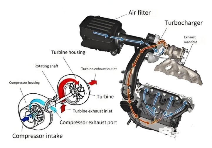
A turbocharger increases engine power by forcing extra air into the combustion chamber, allowing more fuel to be burned, thus producing more power for a given engine displacement. It consists of a turbine and compressor connected by a shaft, with exhaust gases driving the turbine to spin the compressor, which compresses intake air. This process enhances combustion efficiency, boosts torque, and improves fuel economy in downsized engines. Turbochargers typically operate at high speeds, with rotational speeds ranging from 100,000 to 300,000 RPM, depending on the design and application.
Main Components of a Turbocharger
The turbocharger is a complex assembly of components working in unison to achieve its function. The primary components include the turbine, compressor, shaft, bearing system, housings, and auxiliary components such as wastegates and blow-off valves. Below is a detailed breakdown of these components and their roles.
Turbine
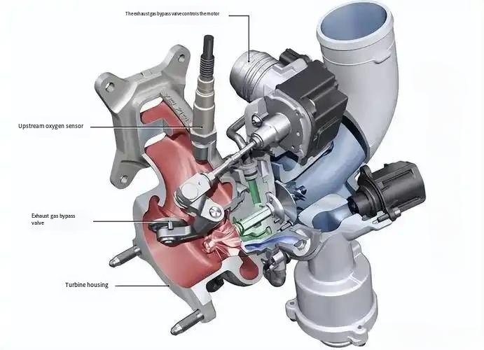
The turbine is the driving force of the turbocharger, converting exhaust gas energy into mechanical work. It consists of the turbine wheel and turbine housing.
- Turbine Wheel: The turbine wheel is a radial-flow turbine impeller that converts the kinetic and thermal energy of exhaust gases into rotational energy. It typically operates at temperatures between 900°C and 1,000°C and is made from high-temperature-resistant alloys such as Inconel or Ni-Resist to withstand extreme conditions. The wheel’s diameter typically ranges from 50 mm to 100 mm, depending on the turbocharger size.
- Turbine Housing: The turbine housing directs exhaust gases to the turbine wheel. It features a volute (spiral) design to optimize gas flow and is typically made from cast iron or Ni-Resist to endure high exhaust temperatures. The housing’s Area-to-Radius (A/R) ratio, typically between 0.8 and 1.3, influences turbine performance, with smaller ratios enabling faster spool-up and larger ratios reducing backpressure at high RPMs.
Compressor
The compressor is responsible for drawing in and compressing ambient air, increasing its pressure and density before it enters the engine’s combustion chamber.
- Compressor Wheel: The compressor wheel, also a radial-flow impeller, draws in air and accelerates it outward, compressing it against the compressor housing. It is typically made from lightweight aluminum alloys or, in high-performance applications, Inconel. Compressor wheel diameters range from 60 mm to 120 mm, with larger wheels providing higher airflow but potentially increasing turbo lag.
- Compressor Housing: The compressor housing contains the compressor wheel and directs compressed air to the engine intake. It is usually made from aluminum for weight reduction and features a volute design to optimize airflow. The housing includes an inlet (inducer) and outlet (exducer), with the A/R ratio typically ranging from 0.6 to 1.0 to balance efficiency and response.
Shaft and Bearing System
The shaft and bearing system connect the turbine and compressor, ensuring smooth rotation at high speeds while managing thermal and mechanical stresses.
- Shaft: The shaft is a precision-engineered component that connects the turbine and compressor wheels, transmitting rotational energy. It is typically made from high-strength steel and must be balanced to prevent vibrations at speeds up to 300,000 RPM. Shaft length varies from 100 mm to 150 mm, depending on turbocharger size.
- Bearing System: The bearing system supports the shaft and includes journal bearings, thrust bearings, and, in some cases, ball bearings. Journal bearings, often made from brass or bronze, use pressurized engine oil for lubrication, with oil pressure requirements of 2–4 bar. Thrust bearings manage axial loads, while ball bearings, used in high-performance turbochargers, reduce friction and improve spool-up time by up to 15%. The bearing housing, typically cast iron or aluminum, contains oil and sometimes water-cooling passages to manage heat.
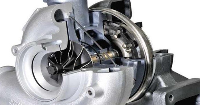
Center Housing Rotating Assembly (CHRA)
The Center Housing Rotating Assembly (CHRA) is the core of the turbocharger, integrating the shaft, bearings, and seals into a single unit. The CHRA is housed in the bearing housing, which provides structural support and contains oil and coolant passages. It ensures precise alignment of the rotating components and is critical for turbocharger reliability. The CHRA is dynamically balanced to within 0.01 ounce-inch to minimize vibration and wear.
Auxiliary Components
Auxiliary components enhance turbocharger performance and protect the engine and turbocharger from damage.
- Wastegate: The wastegate regulates boost pressure by diverting excess exhaust gases away from the turbine wheel. It can be internal (integrated into the turbine housing) or external, with actuation via pneumatic or electronic systems. Wastegates typically open at boost pressures of 1.0–2.0 bar to prevent overboost.
- Blow-Off Valve (BOV): Also known as a bypass valve, the BOV prevents compressor surge by venting excess pressure from the compressor side when the throttle closes. It is typically located between the compressor and throttle body and operates at pressures above 1.5 bar.
- Intercooler: The intercooler cools compressed air, increasing its density and reducing the risk of engine knock. It can reduce air temperature by 20–50°C, improving power output by 5–10%.
Turbocharger Component Specifications
The following table summarizes key specifications for turbocharger components, providing a technical reference for their design and function.
| Component | Material | Typical Size/Range | Operating Condition |
|---|---|---|---|
| Turbine Wheel | Inconel, Ni-Resist | 50–100 mm diameter | 900–1,000°C, 100,000–300,000 RPM |
| Turbine Housing | Cast Iron, Ni-Resist | A/R Ratio: 0.8–1.3 | High exhaust pressure, 900–1,000°C |
| Compressor Wheel | Aluminum, Inconel | 60–120 mm diameter | 100,000–300,000 RPM |
| Compressor Housing | Aluminum | A/R Ratio: 0.6–1.0 | Intake air pressure: 1.0–2.0 bar |
| Shaft | High-Strength Steel | 100–150 mm length | 100,000–300,000 RPM |
| Bearing System | Brass, Bronze, Ball Bearings | Oil Pressure: 2–4 bar | High-speed rotation, axial loads |
Component Interactions and System Dynamics
The turbocharger’s components work together in a highly coordinated manner. Exhaust gases enter the turbine housing, spinning the turbine wheel, which drives the shaft. The shaft, in turn, rotates the compressor wheel, which compresses intake air. The bearing system ensures smooth operation, while the wastegate and blow-off valve regulate pressures to prevent damage. The intercooler optimizes air density for combustion. This system’s efficiency depends on precise engineering, with component tolerances often within 0.01 mm to ensure balance and durability at high speeds.
Common Issues and Considerations
While turbochargers enhance engine performance, they introduce specific challenges that must be addressed for reliable operation.
- Turbo Lag: The delay between throttle input and turbo response, caused by the time required for exhaust gases to spin the turbine, can affect drivability. Smaller turbochargers or ball-bearing systems can reduce lag by up to 20%.
- Heat Management: High exhaust temperatures can cause thermal stress, potentially leading to component wear. Cooling systems, such as water-cooled bearing housings, mitigate this issue.
- Oil Contamination: Contaminated engine oil can damage bearings, reducing turbocharger lifespan. Regular oil changes with high-quality oil (viscosity: 5W-30 or 10W-40) are essential.
- Compressor Surge: Sudden throttle closure can cause pressure buildup in the compressor, leading to surge. Blow-off valves prevent this by venting excess pressure.
Applications of Turbochargers
Turbochargers are widely used in automotive, marine, locomotive, and industrial applications. In automotive engines, they enable smaller engines (e.g., 1.4L) to produce power equivalent to larger naturally aspirated engines (e.g., 2.5L), improving fuel economy by up to 20%. In diesel engines, turbochargers are critical for achieving high power-to-weight ratios, with boost pressures often exceeding 2.0 bar in heavy-duty applications. Aircraft turbochargers maintain engine performance at high altitudes by compensating for reduced air density.
Conclusion
The turbocharger is a sophisticated device that enhances engine performance through a carefully engineered system of components. The turbine, compressor, shaft, bearing system, and auxiliary components like wastegates and blow-off valves work together to deliver increased power, efficiency, and responsiveness. Understanding the structure, specifications, and potential challenges of turbochargers is essential for engineers, mechanics, and enthusiasts aiming to optimize engine performance. By addressing issues like turbo lag and heat management, turbochargers can reliably deliver significant performance benefits across various applications.