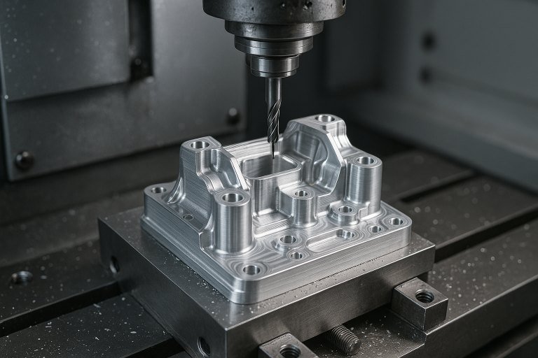
5-axis CNC machining is a high-precision manufacturing technology that enables complex parts to be machined in a single setup by controlling five axes of motion simultaneously. This article explores the main types of 5-axis CNC machining, categorized by rotary axis location, motion control, and machine structure. Each type is analyzed for its features, applications, advantages, and limitations, providing a comprehensive guide for selecting the appropriate method based on part complexity, size, material, and precision requirements.
Overview of 5-Axis CNC Machining
5-axis CNC machining involves three linear axes (X, Y, Z) and two rotary axes, which allow the tool or workpiece to be oriented at various angles. This capability reduces setup times, improves accuracy, and enables the production of complex geometries that are difficult or impossible with 3-axis or 4-axis systems. The technology is widely used in industries such as aerospace, automotive, medical, and mold manufacturing, where precision and efficiency are critical.
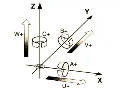
The five axes typically include:
- X-axis: Linear movement along the horizontal plane (left-right).
- Y-axis: Linear movement along the horizontal plane (front-back).
- Z-axis: Linear movement along the vertical plane (up-down).
- Rotary axes (A, B, or C): Rotational movement around the X, Y, or Z axes, respectively.
The configuration of these rotary axes and the machine’s structure define the type of 5-axis CNC machining, each suited to specific applications and part requirements.
Classification by Rotary Axis Location
The placement of the rotary axes—whether on the worktable or the spindle head—determines the machine’s structure and its suitability for different machining tasks. There are three primary configurations: table rotary, spindle head rotary, and hybrid rotary.
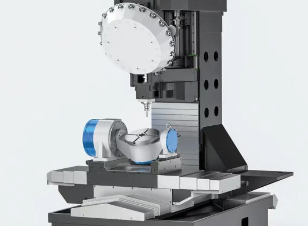
Table Rotary Configuration
In the table rotary configuration, the two rotary axes are integrated into the worktable, while the cutting tool moves along the three linear axes (X, Y, Z). The workpiece rotates to achieve multi-angle machining.
Common Structures:
- A-axis + C-axis Table: The A-axis rotates around the X-axis (tilt angle typically ±30° to ±120°), and the C-axis rotates 360° around the Z-axis. This forms a dual-axis rotary table, often referred to as a trunnion table.
- B-axis + C-axis Table: The B-axis rotates around the Y-axis, and the C-axis rotates around the Z-axis. This setup is ideal for parts requiring significant tilt angles.
Advantages:
- High tool rigidity due to the stationary spindle, enabling heavy cutting.
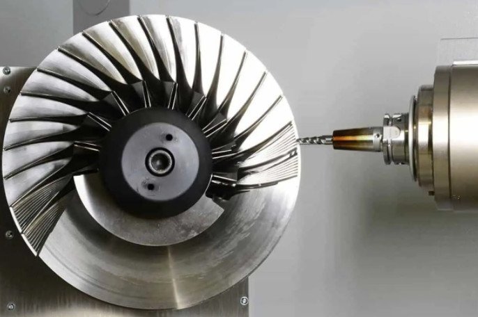
- Suitable for large or heavy parts, such as aerospace components (e.g., turbine blades).
- Allows the use of longer or larger-diameter tools since the spindle does not rotate.
Limitations:
- Limited table size restricts the machining of very large workpieces.
- Worktable load capacity may constrain heavy part machining.
Applications: This configuration is ideal for small to medium-sized parts with complex geometries, such as impellers, blisks, and medical implants.
Spindle Head Rotary Configuration
In this setup, the two rotary axes are integrated into the spindle head, and the workpiece remains stationary on the table. The tool adjusts its angle through the spindle’s rotation and tilt.
Common Structures:
- A-axis + B-axis Spindle Head: The A-axis rotates around the X-axis, and the B-axis rotates around the Y-axis, allowing flexible tool orientation.
Advantages:
- High workpiece load capacity, suitable for large or heavy parts like molds or marine components.
- Unrestricted table size, accommodating oversized workpieces.
Limitations:
- Complex spindle head design reduces rigidity, potentially causing vibration during high-speed cutting.
- Best suited for medium cutting loads rather than heavy machining.
Applications: This configuration excels in machining large molds, automotive body panels, and structural components for ships or aircraft.
Hybrid Rotary Configuration
The hybrid rotary configuration combines one rotary axis on the worktable and one on the spindle head, offering enhanced flexibility for complex machining tasks.
Common Structures:
- C-axis Table + A-axis Spindle Head: The C-axis rotates the worktable around the Z-axis, while the A-axis tilts the spindle head around the X-axis.
Advantages:
- Combines the benefits of table and spindle head rotation, enabling machining of complex surfaces without interference.
- Ideal for parts requiring simultaneous tool and workpiece adjustment.
Limitations:
- Higher complexity increases machine cost and maintenance requirements.
- Requires advanced programming and operator expertise.
Applications: This setup is used for intricate parts like turbine impellers, aerospace blades, and complex medical devices.
Classification by Motion Control Method
5-axis CNC machines can also be categorized by how the axes are controlled: full 5-axis simultaneous machining or 3+2 axis positional machining.
Full 5-Axis Simultaneous Machining
In full 5-axis simultaneous machining, all five axes (X, Y, Z, and two rotary axes) move concurrently, allowing real-time adjustment of the tool’s position and orientation.
Key Parameters:
- Rotary Axis Speed: Typically 20–100 RPM for C-axis, depending on machine design.
- Positioning Accuracy: ±0.002 mm for linear axes, ±0.005° for rotary axes.
- Tool Path Complexity: Supports continuous, smooth tool paths for complex surfaces.
Advantages:
- Capable of machining complex, freeform surfaces like turbine blades or sculptured molds.
- Reduces tool interference and improves surface finish and accuracy.
Applications: Aerospace components (e.g., compressor blades), high-precision molds, and medical implants.
3+2 Axis Positional Machining
In 3+2 axis machining, the two rotary axes position the workpiece or tool at a fixed angle, and then the three linear axes perform the cutting. This is essentially 3-axis machining with angular positioning.
Key Parameters:
- Rotary Axis Positioning Time: 1–5 seconds per angle adjustment.
- Positioning Accuracy: Similar to 5-axis simultaneous machining but with simpler tool paths.
- Tool Path Complexity: Limited to planar or prismatic surfaces.
Advantages:
- Simpler programming and lower computational requirements compared to full 5-axis machining.
- Higher rigidity due to fixed tool angles, suitable for multi-sided parts.
Limitations:
- Cannot machine continuous complex surfaces.
- Requires machine stops for angle adjustments, increasing cycle time.
Applications: Multi-sided parts like housings, brackets, and engine blocks.
Classification by Machine Structure
The physical structure of the 5-axis CNC machine influences its suitability for specific applications. The following table summarizes the main machine types, their features, and applications.
| Structure Type | Features | Typical Applications |
|---|---|---|
| Vertical 5-Axis Machining Center | Vertical spindle, horizontal table, compact design, suitable for small to medium parts. | Molds, precision parts, medical components. |
| Horizontal 5-Axis Machining Center | Horizontal spindle, rotatable table, excellent chip evacuation, ideal for large parts. | Aerospace engine casings, large housings. |
| Gantry 5-Axis Machining Center | Gantry frame, high rigidity, large table area, suited for oversized parts. | Wind turbine blade molds, marine components, rail parts. |
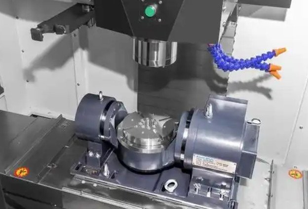
| Cradle-Type 5-Axis Machining Center | Cradle-shaped table with dual-axis rotation, compact, ideal for complex small parts. | Impellers, medical devices, aerospace components. |
Selecting the Right 5-Axis CNC Machining Type
Choosing the appropriate 5-axis CNC machining type depends on several factors:
- Part Complexity: Full 5-axis simultaneous machining is best for complex, freeform surfaces, while 3+2 axis machining suits multi-sided prismatic parts.
- Part Size and Weight: Spindle head rotary or gantry-type machines are ideal for large or heavy parts, while table rotary machines suit smaller components.
- Material: Heavy-cutting materials like titanium require table rotary configurations for better rigidity, while lighter materials like aluminum can use spindle head rotary machines.
- Precision Requirements: Full 5-axis machining offers superior surface finish and accuracy for high-precision parts.
- Cost: 3+2 axis machining and table rotary configurations are generally more cost-effective due to simpler programming and machine design.
For example, aerospace turbine blades benefit from hybrid rotary configurations with full 5-axis machining, while automotive molds may use spindle head rotary machines with 3+2 axis machining for cost efficiency.
Conclusion
5-axis CNC machining encompasses a range of configurations and control methods, each tailored to specific manufacturing needs. Table rotary, spindle head rotary, and hybrid rotary configurations offer distinct advantages for different part sizes and complexities. Full 5-axis simultaneous machining excels in producing complex surfaces, while 3+2 axis machining provides a cost-effective solution for multi-sided parts. Machine structures like vertical, horizontal, gantry, and cradle-type further enhance application versatility. By understanding these types and their parameters, manufacturers can optimize their processes for industries like aerospace, automotive, and medical, achieving high precision and efficiency.