Valve body machining is a critical process in manufacturing components that regulate fluid flow in industries such as oil and gas, automotive, aerospace, and power generation. This article provides a detailed, technical overview of the valve body machining process, covering material selection, machining techniques, precision requirements, and quality control measures. The focus is on delivering a systematic and professional explanation of the processes involved, ensuring clarity and depth for engineers, manufacturers, and industry professionals.
Overview of Valve Body Machining
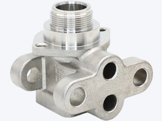
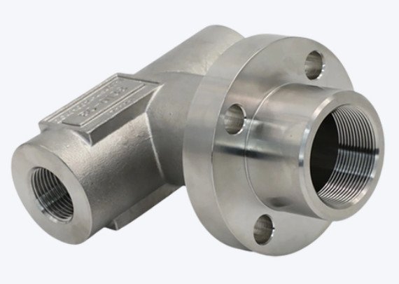
Valve bodies are the primary structural components of valves, housing internal elements like seats, stems, and actuators. Machining valve bodies involves transforming raw materials—typically castings or forgings—into finished components with precise dimensions and surface finishes. The process requires advanced equipment, such as CNC machines, and adherence to strict tolerances to ensure functionality and reliability in demanding applications. The machining process typically includes turning, milling, drilling, and grinding, tailored to the valve’s design and application requirements.
The primary goal is to achieve dimensional accuracy, surface quality, and structural integrity. Valve bodies must withstand high pressures, temperatures, and corrosive environments, making material selection and machining precision paramount. The process is often customized based on valve type (e.g., ball, gate, butterfly, or check valves) and industry standards such as API, ASME, or ISO.
Material Selection for Valve Bodies
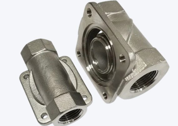
Material selection is the first step in valve body machining, as it determines the component’s durability, corrosion resistance, and machinability. Common materials include:
- Carbon Steel (e.g., WCB): Used for general-purpose valves due to its strength and cost-effectiveness. Suitable for moderate temperatures and pressures.
- Stainless Steel (e.g., 316, 304): Preferred for corrosive environments, such as chemical processing or marine applications, due to its resistance to rust and oxidation.
- Cast Iron: Common for low-pressure applications like water systems, offering good machinability but limited corrosion resistance.
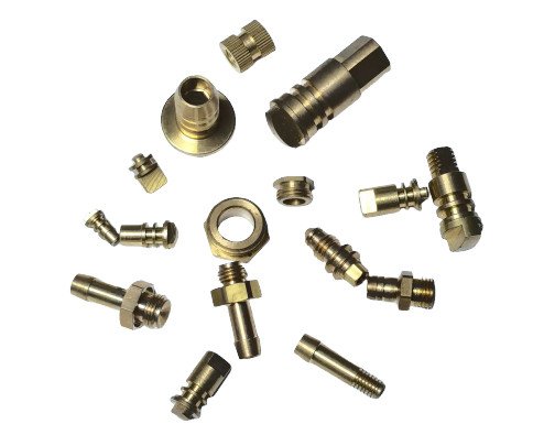
- Brass and Bronze: Used in smaller valves or applications requiring good corrosion resistance and machinability, such as plumbing or low-pressure gas systems.
- Exotic Alloys (e.g., Inconel, Hastelloy): Employed in extreme conditions, such as high-temperature or high-corrosion environments in oil and gas or aerospace industries.
- Non-Metallic Materials (e.g., PEEK): Used in specialized applications requiring chemical resistance and lightweight properties, such as medical devices.
Material choice depends on operating conditions, including pressure (up to 10,000 psi for high-pressure valves), temperature (ranging from -196°C for cryogenic applications to 600°C for high-temperature systems), and fluid type (e.g., water, oil, gas, or corrosive chemicals). Machinability is also a key factor, as harder materials like stainless steel or Inconel require specialized tooling and slower cutting speeds, impacting production time and cost.
Machining Processes and Techniques
Valve body machining involves multiple processes to achieve the required geometry, tolerances, and surface finish. The primary techniques are outlined below, with specific parameters for clarity.
CNC Turning
CNC turning is used to machine cylindrical features, such as valve seat holes, bonnet openings, and flange faces. Turning machines rotate the workpiece while a cutting tool removes material. For valve bodies, typical parameters include:
- Spindle Speed: 500–8,000 RPM, depending on material (e.g., 800 RPM for stainless steel, 2,000 RPM for aluminum).
- Feed Rate: 0.1–0.3 mm/rev for finishing cuts, 0.3–0.5 mm/rev for roughing.
- Depth of Cut: 0.5–2 mm for roughing, 0.1–0.5 mm for finishing.
- Tooling: Carbide or polycrystalline diamond (PCD) inserts for high-silicon aluminum or exotic alloys.
Turning ensures coaxiality between critical features, such as the valve seat and bonnet, with tolerances as tight as ±0.001 mm for high-precision applications.
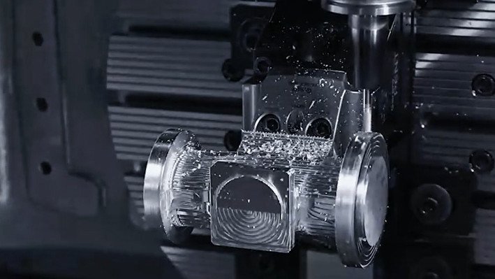
CNC Milling
CNC milling is employed for non-cylindrical features, such as bolt holes, grooves, and complex geometries on valve flanges. Multi-axis milling (4- or 5-axis) is often used for intricate valve bodies, allowing machining in a single setup to reduce errors. Parameters include:
- Spindle Speed: 1,000–10,000 RPM, adjusted for material hardness.
- Feed Rate: 0.05–0.2 mm/tooth for finishing, 0.2–0.4 mm/tooth for roughing.
- Tooling: High-speed steel (HSS) or carbide end mills, with coolant to reduce heat buildup.
Milling ensures perpendicularity of bolt hole centerlines to flange faces, typically within 1° as per industry standards.
Drilling and Reaming
Drilling creates ports and bolt holes, while reaming ensures precise bore diameters and surface finishes. For valve body spool bores, reaming with PCD-tipped tools is common to achieve surface finishes of 0.8–1.25 µm Ra. Parameters include:
- Drill Speed: 500–2,000 RPM, depending on material and diameter (e.g., 7.6–10.6 mm for spool bores).
- Feed Rate: 0.1–0.3 mm/rev for drilling, 0.2–0.3 mm/rev for reaming.
- Tolerance: ±0.002 mm for spool bores to ensure proper valve operation.
Interrupted cuts in cast aluminum valve bodies can cause tool chipping, requiring careful feed rate adjustments.
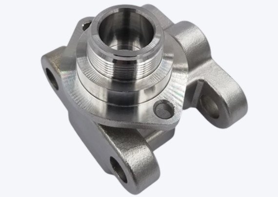
Grinding and Finishing
Grinding and honing are used for final surface finishing, particularly for valve seats and sealing surfaces. These processes achieve surface finishes of 0.4–0.8 µm Ra and tolerances of ±0.001 mm. Grinding wheels (e.g., CBN or diamond) are used for hard materials like stainless steel or Inconel. Finishing ensures leak-free performance and compatibility with valve members.
Precision and Tolerances
Precision is critical in valve body machining to ensure functionality and reliability. Key tolerances and requirements include:
| Feature | Tolerance | Surface Finish (Ra) | Application |
|---|---|---|---|
| Valve Seat Hole | ±0.001–0.005 mm | 0.4–0.8 µm | Ensures sealing with valve member |
| Bolt Hole | ±0.01 mm | 1.6–3.2 µm | Secures flange connections |
| Bonnet Opening | ±0.005 mm | 0.8–1.6 µm | Aligns with actuator |
| Spool Bore | ±0.002 mm | 0.8–1.25 µm | Ensures smooth valve operation |
Coaxiality between the valve seat and bonnet opening is critical, typically maintained within 0.01 mm. Perpendicularity of flange bolt holes to the end face must not exceed 1°, as specified by standards like API 6D.
Quality Control and Testing
Quality control ensures that machined valve bodies meet design specifications and industry standards. Key methods include:
- Coordinate Measuring Machine (CMM) Inspection: Verifies dimensional accuracy with precision up to ±0.001 mm.
- Surface Roughness Testing: Measures surface finish using profilometers to ensure compliance with required Ra values.
- Pressure and Leak Testing: Simulates operating conditions (e.g., 1.5x design pressure) to verify sealing performance.
- Non-Destructive Testing (NDT): Includes ultrasonic and liquid penetrant tests to detect internal defects or cracks.
Traceability of materials and processes is maintained through documentation, adhering to standards like 10 CFR 50 Appendix B for nuclear valves or AS9100 for aerospace applications.
Equipment and Tooling
Valve body machining requires specialized equipment and tooling to achieve precision and efficiency. Common machines include:
- CNC Lathes: For turning operations, with chucking diameters up to 36 inches and steady rest capacities up to 24 inches.
- Horizontal Machining Centers (HMCs): Equipped with multi-pallet systems for high-volume production, capable of 5-axis machining.
- Vertical Mills: Used for smaller valve bodies, with tolerances as tight as ±0.001 mm.
Tooling includes carbide inserts, PCD reamers, and CBN grinding wheels. Advanced features like coolant-through tools and Renishaw probes enhance precision and reduce setup times.
Applications of Machined Valve Bodies
Machined valve bodies are used across various industries, each with specific requirements:
| Industry | Valve Type | Material | Key Requirements |
|---|---|---|---|
| Oil and Gas | Ball, Gate, Check | Stainless Steel, Inconel | High pressure (up to 10,000 psi), corrosion resistance |
| Automotive | Transmission Valves | Aluminum | Tight tolerances (±0.002 mm), smooth surface finish |
| Aerospace | Hydraulic Valves | Titanium, PEEK | Lightweight, high precision |
| Water Treatment | Butterfly, Gate | Cast Iron, Brass | Cost-effectiveness, corrosion resistance |
Each application demands tailored machining processes to meet performance and regulatory requirements.
Conclusion
Valve body machining is a complex, precision-driven process that requires careful material selection, advanced CNC techniques, and rigorous quality control. By adhering to strict tolerances and industry standards, manufacturers produce reliable, high-performance valve bodies for critical applications. This article has provided a comprehensive, technical overview of the process, emphasizing systematic approaches and detailed parameters to ensure clarity and professionalism.